49
SERVICING
isar - Installation and Servicing
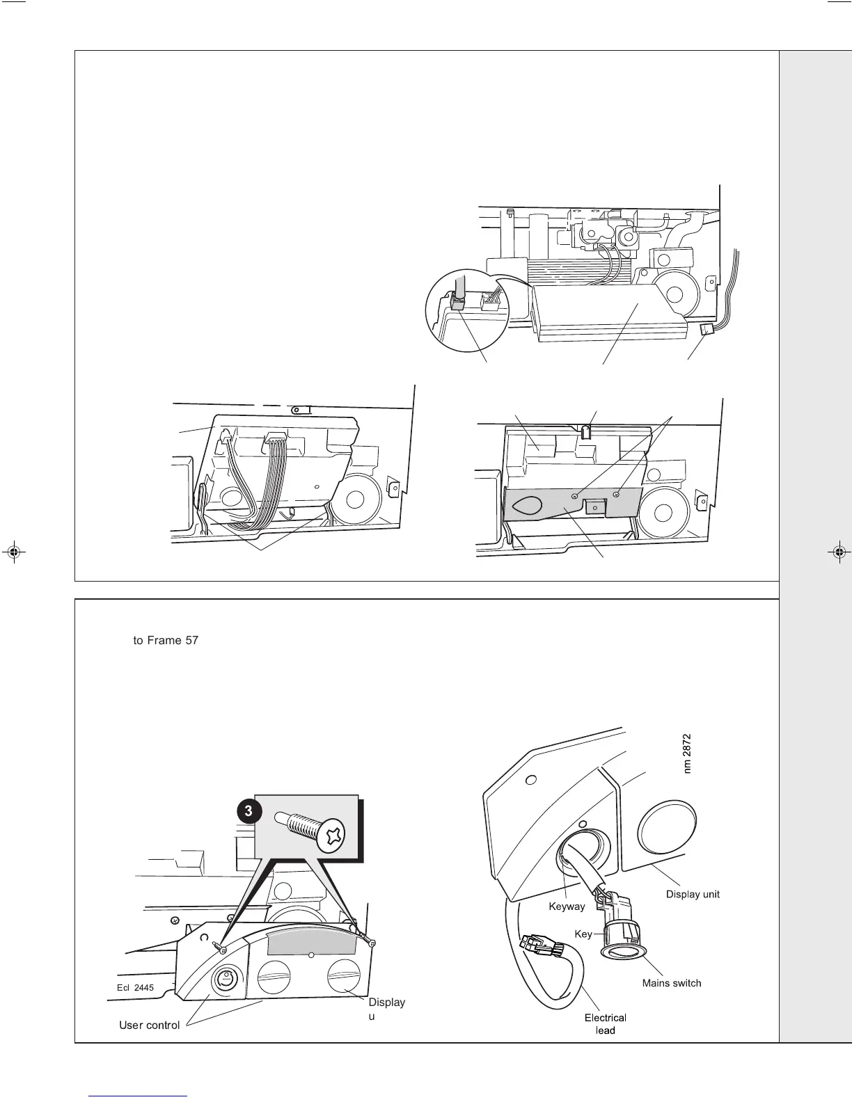
Screws
C.
B .
A.
Hinge arms
Control box mounting bracket
Electrical lead
Control box
Control box
Control
box
nm7541
Low voltage lead
Clamp
!
Ecl 2445
Display
unit
User control
1. Refer to Frame 57.
2. Remove the casing front & bottom panel.
Refer to Frames 49 & 50.
3. Remove the 2 screws and allow the user control to lower.
4. Push out the mains switch from the rear, as shown.
5. Fit the new switch, ensuring that the electrical leads are
72
MAINS SWITCH REPLACEMENT
71
CONTROL BOX REPLACEMENT
1. Refer to Frame 57.
2. Remove the casing front & bottom panel.
Refer to Frames 49 & 50.
3. Swing the control box down into the servicing position.
Refer to Frame 51.
4. Unplug the user control electrical lead and low voltage
lead from the control box and remove the control. Refer
to diagram A.
5. Return the control box to the working position and
secure with the clamp. Unscrew the mounting bracket
screws to remove the bracket. Refer to diagram B.
6. Release the clamp and carefully remove the control
box from the hinge arms. Refer to diagram C.
7. Unplug all the electrical wiring from the control box and
remove.
8. Transfer mounting bracket and hinge arms to the new
control box.
9. Reassemble in reverse order, ensuring that the control box
is located correctly in the housing before reconnecting the
electrical wiring.
10. Check operation of the boiler. Refer to Frame 57.
replaced on the correct terminals (refer to Frame 36) and
the key on the switch is correctly aligned with the slot in the
plastic moulding.
6. Reassemble in reverse order.
7. Check operation of the boiler. Refer to Frame 57.
SERVICING
203319-3.pmd 27/03/2008, 08:1549
 Loading...