43
SERVICING
isar - Installation and Servicing
Gasket
Orifice plate
Ecl 2373
5
3
7
4
57
REPLACEMENT OF COMPONENTS
GENERAL
When replacing ANY component
1. Isolate the electricity supply.
2. Turn off the gas supply.
3. Remove the boiler front panel. Refer to Frame 49.
After replacing ANY component check operation of the boiler,
including gas soundness, gas rate and combustion test.
1. Refer to Frame 57.
2. Remove the boiler front and sealing panels. Refer to
Frames 49 & 50.
3. Drain down the boiler. Refer to Frame 77.
4. Unplug the electrical lead.
5. Unscrew the thermistor.
6. Fit the new thermistor using the sealing washer
provided.
7. Reassemble in the reverse order.
8. Check the operation of the boiler.
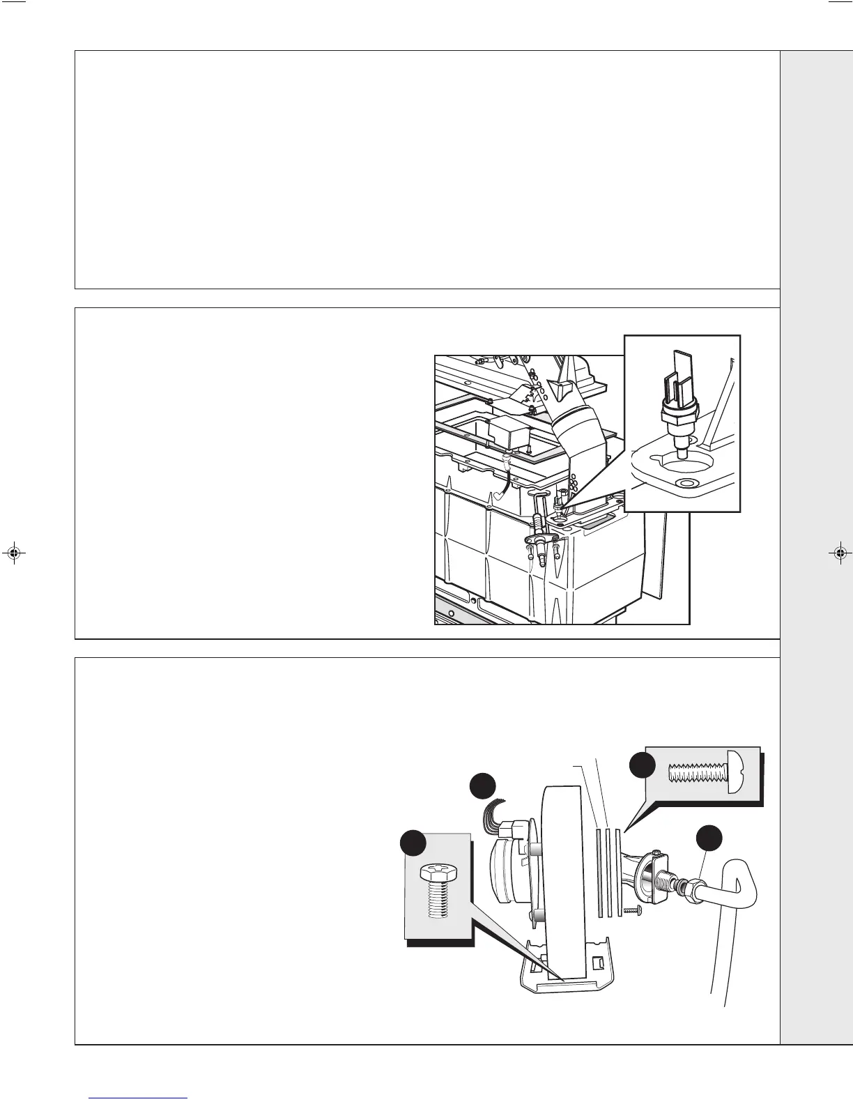
58
DRY FIRE THERMISTOR REPLACEMENT
59
FAN REPLACEMENT
1. Refer to Frame 57.
2. Remove the boiler front and sealing panels. Refer to Frames
49 & 50.
3. Disconnect the electrical leads from the fan.
4. Undo the gas pipe union connection to the injector housing.
5. Remove the screw retaining the fan mounting bracket.
6. Remove the fan and venturi assembly. Refer to
Frame 52.
7. Unscrew the 3 screws and remove the venturi
assembly, noting the orientation of the venturi in
relation to the fan body.
8. Transfer the venturi assembly to the new fan,
replacing the gasket if evidence of damage or
deterioration is visible.
9. Fit the new fan / venturi assembly.
10. Reassemble the boiler in reverse order, taking care not to
overtighten the screw on the fan mounting bracket.
11. Check the operation of the boiler. Refer to Frame 57.
IMPORTANT.
When work is complete, the sealing panel, if removed, must
be correctly refitted - ensuring that a good seal is made.
Notes.
1. In order to assist fault finding, the control panel has an
LED diagnostic display. The key to boiler fault conditions
is shown in Frame 84.
2. In order to replace components in Frames 74-82 it is
necessary to drain the boiler. Refer to Frame 77.
THE BOILER MUST NOT BE OPERATED WITHOUT THE SEALING PANEL FITTED
SERVICING
203319-3.pmd 27/03/2008, 08:1543
 Loading...