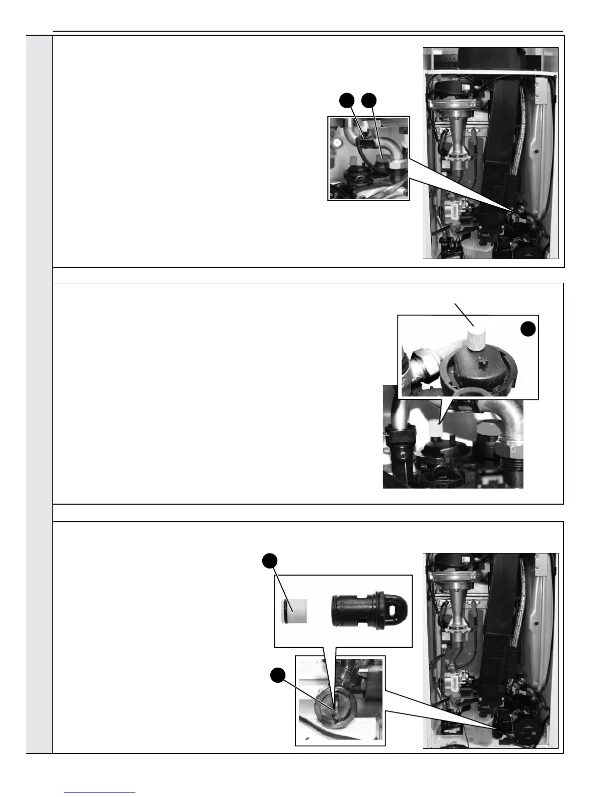
3.23 SAFETY RELIEF VALVE RENEWAL
1. Refer to Section 3.8.
2. Drain the boiler. Refer to Section 3.21.
3. Remove the clip on return thermistor. Refer to Section 3.12.
4. Pull out and remove the clip (positioned behind the safety
valve) retaining the safety valve.
5. Undo the safety valve pipe compression tting positioned
outside the boiler casing.
6. Lift out the safety valve/pipe assembly.
7. Remove the safety valve pipe and transfer to the new safety
valve.
8. Reassemble in reverse order ensuring the retaining clip is
correctly tted, the pipe compression tting retightened and
return thermistor is re-clipped.
9. Rell the boiler. Check operation of the boiler. Refer to
Sections 2.22 & 2.23.
3 4
3.24 PUMP AUTOMATIC AIR VENT REPLACEMENT
1. Refer to Section 3.8.
2. Drain the boiler. Refer to Section 3.21.
3. Remove the expansion vessel. Refer to Section 3.32.
4. Firstly, increase access area by disconnecting the 22mm pipe connection at
top of pump chamber and bottom of heat exchanger and remove pipe.
5. The automatic air vent head is retained in the pump body with a bayonet
connection. The air vent head and oat assembly is removed by turning the
head anti-clockwise (viewed from above) and pulling upwards.
6. Reassembly is the reverse of the above. Ensure the air vent head ‘o’ ring seal
is in place when retting and the new ‘o’ ring is tted to the return pipe top
connection.
7. Ensure the air vent cap is loose.
8. Rell the boiler. Refer to Section 2.15. Check for leaks around the new air vent
joint.
9. Check the operation of the boiler. Refer to Sections 2.22 & 2.23.
5
Dust Cap
3.25 DHW FILTER & DHW FLOW REGULATOR CLEANING/REPLACEMENT
1. Refer to Section 3.8.
2. Drain the DHW system. Refer to Section 3.21.
3. Turn the housing anti clockwise and pull
forward to remove the cartridge.
4. Using a pair of pliers, pull out the plastic lter/
ow regulator.
5. Clean or replace lter as necessary.
6. Reassemble in reverse order.
7. Rell the boiler.
8. Check operation of the boiler. Refer to
Sections 2.22 & 2.23.
3
4
SERVICING
 Loading...


