SERVICING
Ideal Logic Combi - Installation and Servicing
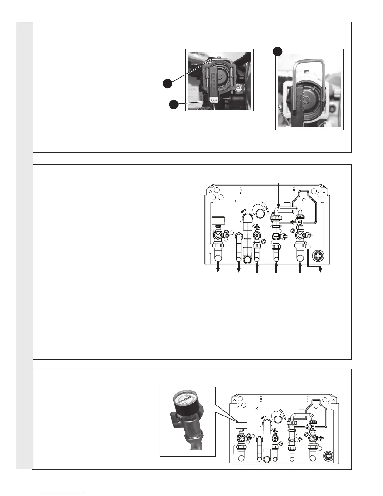
1. Refer to Frame 43.
2. Drain the heating system. Refer to Frame 57.
3. Unscrew the pressure gauge and discard.
4. Fit new pressure gauge, using suitable jointing
compound.
5. Rell the boiler. Refer to Frame 24.
6. Check operation of the boiler. Refer to Frames
32 & 33.
58
PRESSURE GAUGE RENEWAL
57
DRAINING THE BOILER
DOMESTIC HOT WATER CIRCUIT
1. Refer to Frame 43.
2. Close all the DHW water isolating valves on the boiler inlet.
3. To drain the domestic hot water circuit: As there is no direct drain for the domestic hot water circuit, depending on the location
of the boiler, opening the lowest hot water tap may drain this circuit. However it must be noted that some residual water will be
experienced during replacement of components.
4. After replacing any component on the boiler, close tap, close the drain valve and open all system isolating valves (re-pressurise
as appropriate by re-connecting the lling loop, refer to Frame 24) before proceeding to check operation of the boiler.
5. Disconnect lling loop. Refer to Frame 24.
6. Check operation of the boiler. Refer to Frames 32 & 33.
CENTRAL HEATING CIRCUIT
1. Refer to Frame 43.
2. Close all the CH water isolating valves on the boiler inlet.
3. To drain the primary heat exchanger circuit: Open the drain
valve and attach a length of hose to the CH drain point.
4. After replacing any component on the boiler, remove the
hose, close the drain valve and open all system isolating
valves (re-pressurise as appropriate by re-connecting the
lling loop, refer to Frame 24) before proceeding to check
operation of the boiler.
5. Disconnect lling loop. Refer to Frame 24.
6. Check operation of the boiler. Refer to Frames 32 & 33.
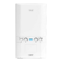
56
DHW FLOW TURBINE SENSOR REPLACEMENT
1. Refer to Frame 43.
2. Drain the DHW system. Refer to Frame 57.
3. Pull off the electrical connection.
4. Using a suitable tool, lift and remove the
retaining clip.
5. Use the clip to ease the turbine sensor from its
housing.
6. Re-assemble in reverse order.
7. Check operation of the boiler. Refer to Frame
32 & 33.
4
3
5
SERVICING
 Loading...