* Only one reduction down to 25mm is allowable per installation
otherwise BS5440-1 2008 dimensions must be followed.
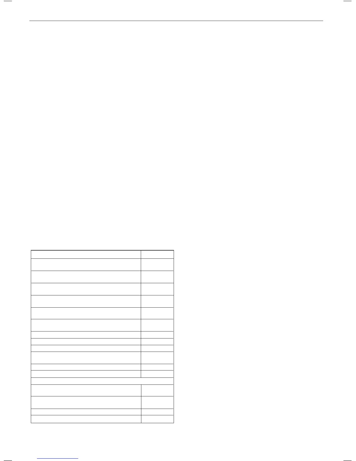
Flue Terminal Positions
Min. Spacing*
1. Directly below, above or alongside an opening
window, air vent or other ventilation opening. 300mm (12”)
2. Below guttering, drain pipes or soil pipes. 25mm ( 1”)*
BS5440-1 2008 75mm (3”)
3. Below eaves. 25mm (1”)*
BS5440-1 2008 200mm (8”)
4. Below balconies or a car port roof. 25mm (1”)*
BS5440-1 2008 200mm (8”)
5. From vertical drain pipes or soil pipes. 25mm (1”)*
BS5440-1 2008 150mm (6”)
6. From an internal or external corner or to a 25mm (1”)*
boundary along side the terminal. BS5440-1 2008 300mm (12”)
7. Above adjacent ground, roof or balcony level. 300mm (12”)
8. From a surface or a boundary facing the terminal. 600mm (24”)
9. From a terminal facing a terminal. 1,200mm (48”)
10. From an opening in a car port
(e.g. door or window) into dwelling. 1,200mm (48”)
11. Vertically from a terminal on the same wall. 1,500mm (60”)
12. Horizontally from a terminal on the wall. 300mm (12”)
13. Above the roof pitch with roof slope of all angles. 300mm (12”)
Above at roof. 300mm (12”)
14. From a single wall face. 300mm (12”)
From corner walls. 300mm (12”)
15. Below velux window 2000mm (79”)
16. Above or side of velux window 600mm (24”)
3. Minimum acceptable spacing from the terminal to
obstructions and ventilation openings are specied in
Table 4.
4. Where the lowest part of the terminal is tted less than 2m
(6’6”) above a balcony, above ground or above a at roof
to which people have access then the terminal MUST be
protected by a purpose designed guard.
Terminal guards are available from boiler suppliers. (Ask for
TFC ue guard model no. K6 - round, plastic coated). In case
of difculty contact:
TFC Group Ltd. Tel. + 44 (0) 01732 351 680
Tower House, Vale Rise Fax. + 44 (0) 01732 354 445
Tonbridge. Kent TN9 1TB www.tfc-group.co.uk
Ensure that the guard is tted centrally.
5. The ue assembly shall be so placed or shielded as to
prevent ignition or damage to any part of any building.
6. The air inlet/products outlet duct and the terminal of the
boiler MUST NOT be closer than 25mm (1”) to combustible
material. Detailed recommendations on the protection of
combustible material are given in BS. 5440-1:2008.
IMPORTANT. It is essential to ensure, in practice, that products
of combustion discharging from the terminal cannot re-enter the
building or buildings through any openings into the building such
as ventilators, windows, doors, or other sources of natural air
inltration, such as forced ventilation openings etc.
If products of combustion re-entry is identied or suspected this
should be immediately investigated and corrected following the
guidance provided in the current Gas Industry Unsafe Situation
Procedure.
TERMINAL
The terminal assembly can be adapted to accommodate various
wall thicknesses. Refer to Frame 10 .
AIR SUPPLY
It is NOT necessary to have a purpose-provided air vent in the
room or internal space in which the boiler is installed. Neither is
it necessary to ventilate a cupboard or compartment in which the
boiler is installed, due to the low surface temperatures of the boiler
casing during operation; therefore the requirements of BS 6798,
Clause 12, and BS 5440:2 may be disregarded.
WATER CIRCULATION SYSTEM
IMPORTANT.
A minimum length of 1 metre of copper pipe MUST be tted to both
ow and return connections from the boiler before connection to
any plastic piping.
The central heating system should be in accordance with BS.6798
and, in addition, for smallbore and microbore systems, BS.5449.
WATER TREATMENT - see Frame 5
BOILER CONTROL INTERLOCKS
Central heating systems controls should be installed to ensure
the boiler is switched off when there is no demand for heating, in
compliance with Building Regulations.
Heating systems utilising full thermostatic radiator valve control
of temperature in individual rooms should also be tted with a
room thermostat controlling the temperature in a space served by
radiators not tted with such a valve.
When thermostatic radiator valves are used, the space heating
temperature control over a living / dining area or hallway having
a heating requirement of at least 10% of the minimum boiler heat
output should be achieved using a room thermostat, whilst other
rooms are individually controlled by thermostatic radiator valves.
However, if the system employs thermostatic radiator valves on all
radiators, or two port valves, then a bypass circuit must be tted
with an automatic bypass valve to ensure a ow of water should all
valves be in the closed position.
ELECTRICAL SUPPLY
WARNING.
This appliance must be earthed.
Wiring external to the appliance MUST be in accordance with
the current I.E.E. (BS.7671) Wiring Regulations and any local
regulations which apply. For IE reference should be made to the
current ETCI rules for electrical installations.
The mains supply to the boiler and system wiring centre shall
be through one common fused double pole isolator and for new
heating systems, and where practical replacement installations, the
isolator shall be situated adjacent to the appliance.
CONDENSATE DRAIN
Refer to Frames 22, 23 & 42
A condensate drain is provided on the boiler. This drain must be
connected to a drainage point on site. All pipework and ttings in
the condensate drainage system MUST be made of plastic - no
other materials may be used.
IMPORTANT.
Installation must be in accordance with BS 6798.
The drain outlet on the boiler is sized for standard 21.5mm (3/4”)
overow pipe. It is a universal tting to allow use of different
brands of pipework.
 Loading...