33
INSTALLATION
Ideal Logic + Combi - Installation and Servicing
29
EXTERNAL ELECTRICAL CONTROLS
The fuse rating should be 3A.
Wiring external to the boiler MUST be in accordance
with the current I.E.E. (BS.7671) Wiring Regulations
and any local regulations.
Frost Protection
If parts of the pipework run outside the house or if
the boiler will be left off for more than a day or so
then a frost thermostat should be wired into the
system.
This is usually done at the programmer, in which
case the programmer selector switches are set to
OFF and all the other controls MUST be left in the
running position.
The frost thermostat should be sited in a cold place
but where it can sense heat from the system.
Note. If the boiler is installed in a garage it may be
necessary to t a pipe thermostat, preferably on the
return pipework.
Earths are not shown for clarity but must never
be omitted.
28
REPLACING PRE-FITTED MAINS CABLE
If it is necessary to use an alternative mains cable to the one pre-tted then
use the following guide.
Replacement wiring should comply with notes in Frame 25.
1. Isolate the mains supply to the boiler.
2. Remove the front panel. Refer to Frame 39.
3. Swing the control box down into the service position. Refer to Frame 45.
4. Remove the live, neutral and earth wires from the terminal block.
5. Loosen the cable clamp and withdraw the mains cable.
6. Route replacement cable back through the cable clamp and grommet and
re-tighten to provide cord anchorage.
7. Connect the live, neutral and earth wires to the terminal strip.
When making the mains electrical connections to the boiler it is important
that the wires are prepared in such a way that the earth conductor
is longer than the current carrying conductors, such that if the cord
anchorage should slip, the current carrying conductors become taut before
the earthing conductor.
8. Swing the control box back up into the operating position and re-t the
front panel ensuring a good seal is made.
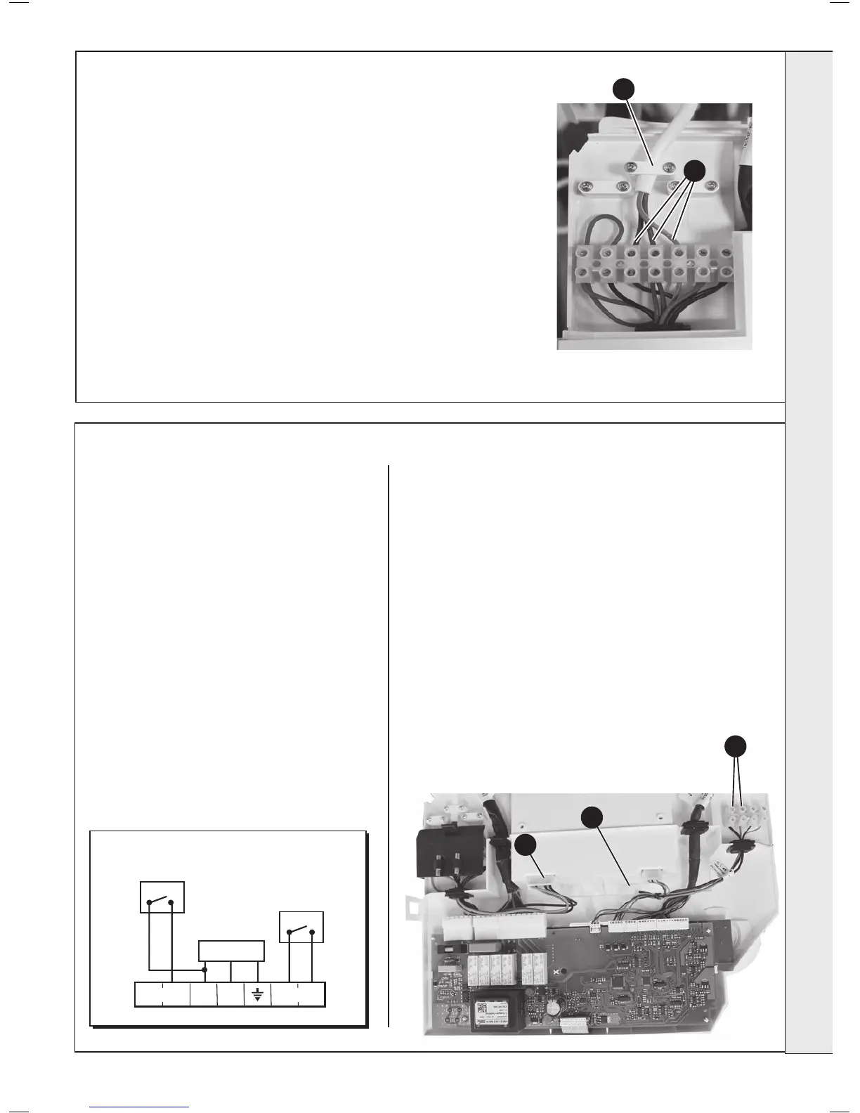
5
6
7
Note. These terminals MUST ONLY be connected to an OpenTherm
Controller. Connecting any other device / control wiring may destroy
the primary PCB.
1. Isolate the mains supply to the boiler.
2. Remove the front panel. Refer to Frame 39.
3. Swing the control box down into the servicing position. Refer to
Frame 45.
4. Remove the control box cover. Refer to Frame 56, no’s 3 and 4.
5. Unclip the 3 way in-line connector containing 2 purple wires and 2
red wires.
6. Connect this 3 way connector to the 3 way connector containing 2
purple wires wired from the 4 way terminal block.
7. Connect the two wires from the OpenTherm Programmable Room
Temperature Control to the two LH connections of the terminal
block as shown.
8. Re-assemble in reverse order.
4
5
INSTALLATION
 Loading...