74
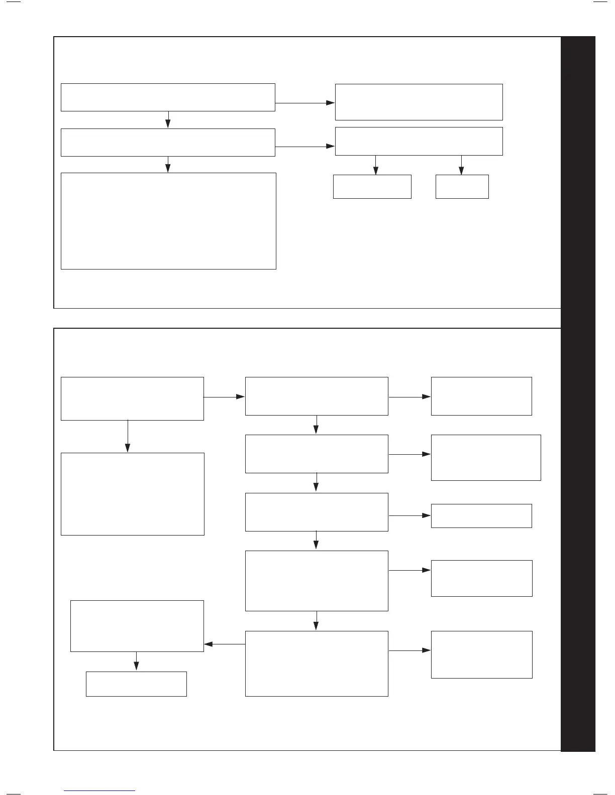
Is the Boiler and CH System lled with water and all
isolation and radiator valves open?
YES
Fill and vent the system and open all
isolation valves, then restart boiler
Is the Flow/Return Differential across the Boiler in
excess of 30°C?
NO
Check that the Pump is rotating freely. Is
the Differential now below 20°C?
YES
NO
Replace the Pump,
then restart boiler
NO
OK, now
restart boiler
YES
75
IGNITION LOCKOUT - 1 CHECK OTHER GAS APPLIANCES WORK -
2 RESTART BOILER - 3 CONTACT INSTALLER
If the boiler is restarted does the
boiler ignite for a short time and
then extinguish?
YES
Is the Gas Pressure available at
the Boiler Inlet (>18 mbar)?
Check the detection electrode
and associated harness for:
continuity, visual condition and
position (Refer to Frame 51).
Check if the condensate pipe is
blocked.
Replace as necessary
NO
Check gas supply and
rectify fault
NO
YES
Is approx 215Vdc supply available
at the Gas Valve? (* See note)
YES
Check spark generator and
associated harness for: continuity
and visual condition. (Refer to
Frame 52) Are these functioning
correctly?
YES
Check ignition electrode and
associated harness for: continuity,
visual condition and position.
(Refer to Frame 50) Are these
functioning correctly?
Check siphon and condensate
drain pipe work for blockage and
rectify if necessary. Boiler now
working OK?
Check wiring connection
from gas valve to PCB for
continuity. If the wiring is
OK then replace the PCB
NO
Replace Spark
Generator and harness
as necessary
NO
Replace Ignition
Electrode and
associated harness as
necessary
NO
Replace Gas Valve
NO
* Note: due to the wave form of the rectied voltage, the reading will vary depending on the type of meter used to measure the
value. In general terms a reading greater than 150V indicates that the correct voltage is supplied to the gas valve.
Unplug gas valve. Is resistance
between outside pins between
4k Ω (± 2)?
YES
Replace Gas Valve
NO
YES
RESTART PROCEDURE - To restart boiler, turn mode knob to restart position and immediately turn knob back to required setting.
RESTART PROCEDURE - To restart boiler, turn mode knob to restart position and immediately turn knob back to required
setting.
Check the Flow and Return Thermistors
(Refer to Frame 69)
Check resistance using a suitable multimeter
connected across the thermistor’s terminal pins
At 25
o
C expect 9,700 - 10,300 Ohms
At 60
o
C expect 2,400 - 2,600 Ohms
At 85
o
C expect 1,000 - 1,100 Ohms
 Loading...