5
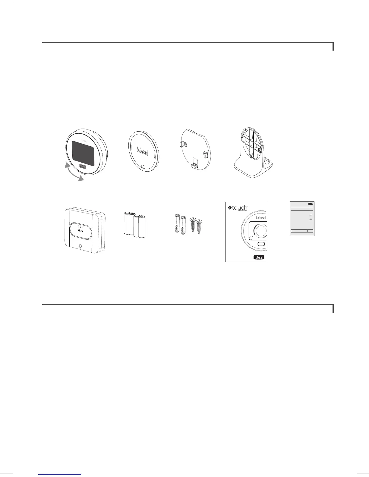
Ideal Touch kit contents
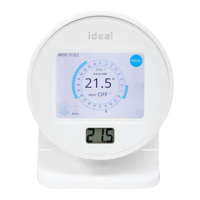
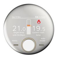
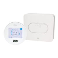
A. Touch thermostat
B. Mounting bracket cover
C. Mounting bracket
D. Desktop stand
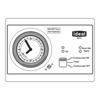
E. Ideal relay transceiver
F. Batteries (AA)
G. Screws and plugs
H. Instructions
I. SAP registration label
Thermostat location guidelines
In-between the Ideal relay transceiver and the Touch thermostat there must be:
• Less than 20 metres
• No more than a total of 3 walls and ceilings
• No large metallic objects (e.g. American fridge/freezer)
• No large mirrors or windows
• No walls running along the RF path
The Touch thermostat must not be within 1 metre of a wifi booster / router and
should not be placed near draughts, in direct sunlight or near heat sources.
You will see the Ideal relay transceiver installed in your home, usually near your hot
water cylinder. This should only be opened and worked on by a qualified electrician.
A B C
E
F
G
H
I
D
IDEAL BOILERS LTD
Model Name:
Model Qualifier:
Touch (Single Zone)
ErP Class V or ErP Class VI
I certify that this boiler is connected to a weather
compensation control as indicated:
Touch enhanced load compensator (Class V)
Touch enhanced load compensator & OS2 weather
compensator temperature sensor (Class VI)
These products are compatible with the boiler and
provide compensation control that has been
permanently enabled. The boiler has been
commissioned in accordance with the manufacturer
instructions which have been supplied to the
householder. The central heating temperature control
knob should normally be set in the mid-position.
Signed: Date:
UIN 217679 A01
Installation guide
Wireless room thermostat
with hot water control
(DHW & single zone CH)
Logic Heat H / Logic System S / Vogue System
 Loading...