DOC No: PN 86880 REV A
13
EAGLEDRIVE ELECTRICAL
CONNECTIONS (CONTINUED)
Common Ground
Main Power IN voltage, control signal inputs, and all outputs use a common
ground. It is possible that ground potential dierences between the power
supply, control voltage source and the other devices (if used) will be forced to the
same ground reference when connected to the EagleDrive. Ensure only one earth
ground is used to avoid ground loops.
Analog DC Control Signal In
-0.3 to 5.1Vdc control input, motor set to zero rpm -0.3 to +0.2V, motor set to 100%
above +5.0V as read with ADC channel on microprocessor Input impedance ~6 kohm,
input is not clamped and must remain below 5.1V max at all times Internal 100k pull
down on input provided positive stop should lead be disconnected.
Input Voltage vs RPM is proportional within a given mains voltage (i.e. % of 5.0V = %
of maximum motor speed as dened by main power in controlled by 8-bit microprocessor
signal, operating open-loop-speed with motor max output current limited.
PWM (Pulse Width Modulation) Speed Control
% Positive duty cycle within 3% to 97% at 20-100Hz frequency results in motor
speed proportional to the input (i.e. % of Positive Duty Cycle = % of maximum
motor speed at dened main power in), motor set to zero rpm 0 to 3% and 97 to
100% controlled by 8-bit microprocessor signal, operating open-loop-speed
with motor max output current limited.
Input impedance ~6 kohm, input is not clamped and must remain within -0.3 to
1.5v (Lo) and +3.5 to 5.1V (Hi) or the motor will be irreparably damaged.
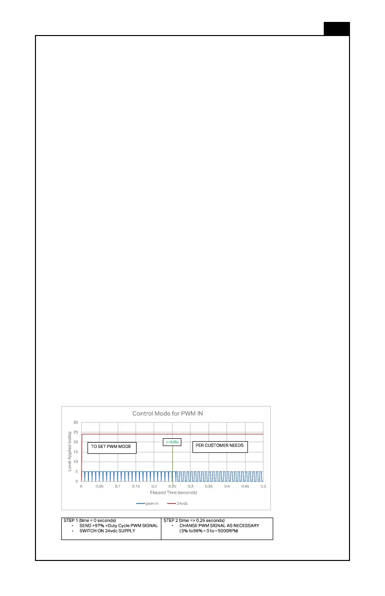
To enable PWM IN the EagleDrive must read a “high” level signal (greater than
97% +Duty Cycle PWM signal) during each application of main power in (when
rmware POST is occurring) to choose PWM IN mode. The EagleDrive will
otherwise default to Analog DC Control Signal IN mode.
Example of Control Signals Necessary to Select PWM IN Mode:
 Loading...