EasyManuals Logo
Home>Inficon>Measuring Instruments>Gemini MPG500

Inficon Gemini MPG500 User Manual

Inficon Gemini MPG500
64 pages
To Next Page IconTo Next Page
To Previous Page IconTo Previous Page
Page #29 background imageLoading...
Page #29 background image
tina83e1-d (2018-12) 29
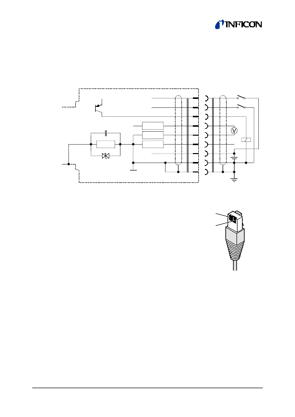
3.2.1 FCC 68, 8-pin Connector
If no sensor cable is available, make one according to the
following diagram. Connect the sensor cable.
3
5
4
1
2
+
+
6
4.7
4.7
Ident
Signal
7
+
8
High active
Low active
HV on
HV on
Electrical connection
Pin 1 Supply (14.5 … 30 V (dc))
Pin 2 Supply common GND
Pin 3 Signal output (measuring signal)
Pin 4 Gauge identification
Pin 5 Signal common
Pin 6 Status signal
Pin 7
*)
High voltage on/off (low active)
Pin 8
*)
High voltage on/off (high active)
*)
MAG only. Pin 7 and 8 are not assigned in
the MPG gauge.
1
8
FCC 68
8-pin

Questions and Answers:

Question and Answer IconNeed help?

Do you have a question about the Inficon Gemini MPG500 and is the answer not in the manual?

Inficon Gemini MPG500 Specifications

General IconGeneral
BrandInficon
ModelGemini MPG500
CategoryMeasuring Instruments
LanguageEnglish

Related product manuals