Inovance MDBUN Series Braking Unit User Manual
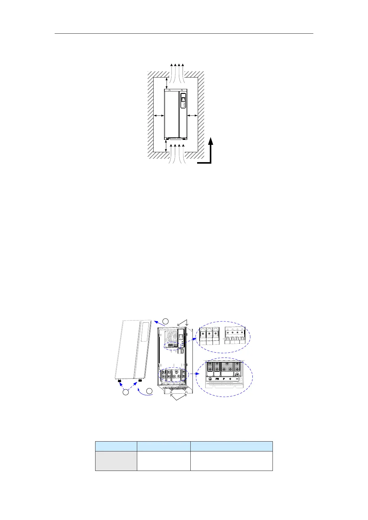
Figure 3-2 Installation clearances of the MDBUN series braking unit
Installed vertically upward
10 cm
5 cm
MDBUN
Hot air
Cold air
10 cm
5 cm
3.1.3 Mechanical Installation Suggestions
Install the braking resistor in a space with good ventilation, because the braking resistor
gets heated when consuming the feedback energy generated during braking.
Install the braking unit upright to facilitate heat dissipation. Do not lay it upside-down or
horizontally.
If multiple braking units are connected to the drive, install them side by side. If one row of
braking units needs to be installed above another row, install an insulation guide plate to
prevent braking units in the lower row to bake those in the upper row.
Ensure that the distance between the braking unit, drive, and other electric device meets
the requirements shown in Figure 3-2.
3.2 Electrical Installation
The following figure shows the terminal arrangement of the braking unit.
Figure 3-3 Terminal arrangement of the braking unit
1
2
3
T/A
T/B
T/C
DI
DO
24V
CO
M
Power wiring
terminal
Control signal
terminal
Mechanical
installation hole
Mechanical
installation hole
Remove the
two screws.
Lift the cover
upward.
Remove the
cover.
3.2.1 Terminal Description
Description of Power Wiring Terminals
Positive and
negative terminals
of the DC bus
Used as the input point of the
common DC bus
 Loading...