Technical Reference
55
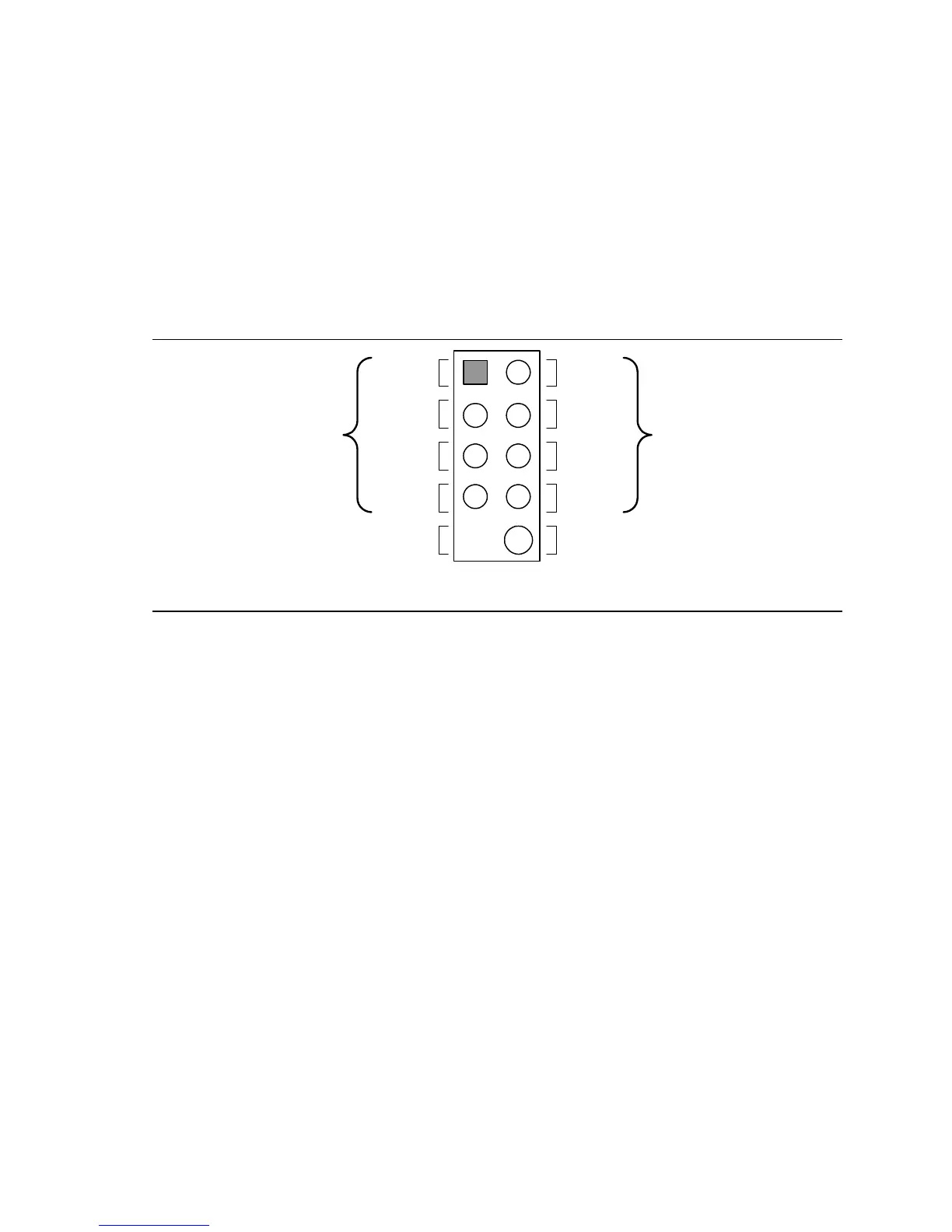
2.7.2.5 Front Panel USB Connectors
Figure 15 is a connection diagram for the front panel USB connectors.
#
INTEGRATOR’S NOTES
• The +5 V DC power on the USB connector is fused.
• Pins 1, 3, 5, and 7 comprise one USB port.
• Pins 2, 4, 6, and 8 comprise one USB port.
• Use only a front panel USB connector that conforms to the USB 2.0 specification for high-
speed USB devices.
• These USB connectors do not support USB anti-theft circuitry.
OM15963
8
6
4
2
7
5
3
1
Key (no pin)
No Connect
10
Power
(+5 V DC)
D−
D+
Ground
D+
Ground
D−
Power
(+5 V DC)
One
USB
Port
One
USB
Port
Figure 15. Connection Diagram for Front Panel USB Connectors
 Loading...