Technical Reference
51
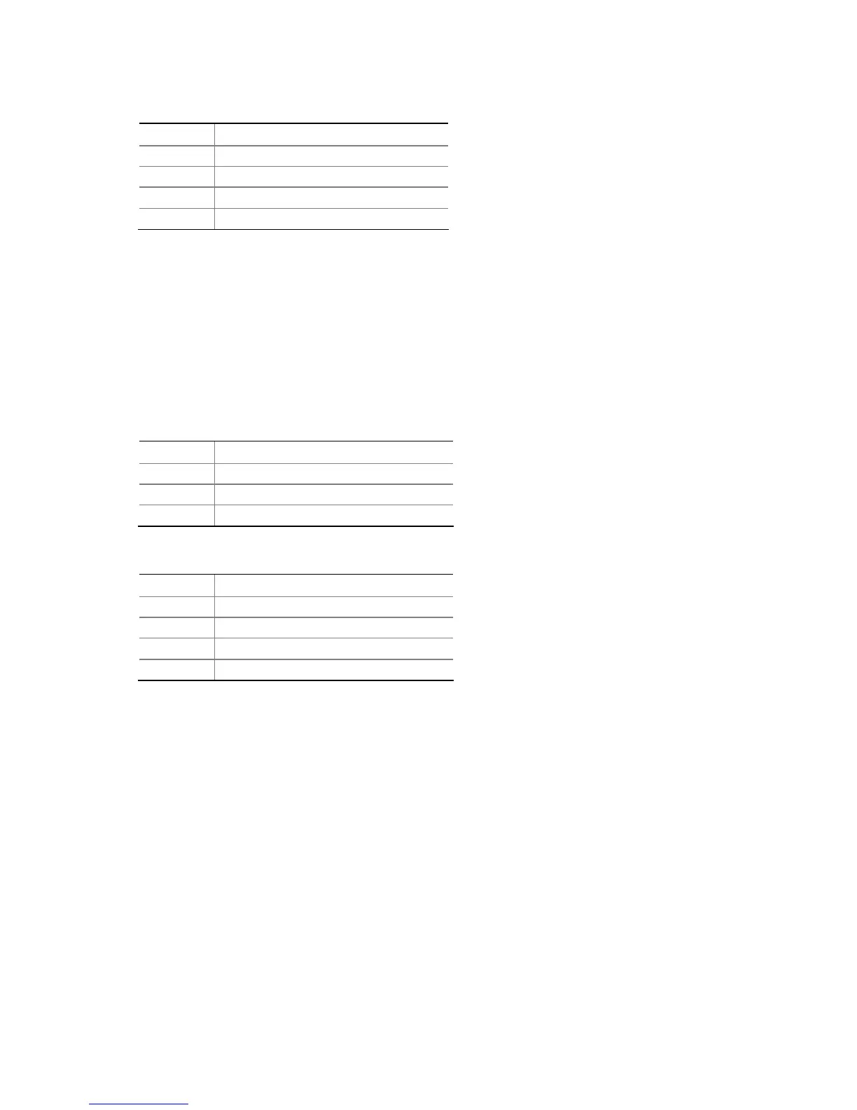
Table 21. Processor Fan Connector
Pin Signal Name
1 Ground
2 +12 V
3 FAN_TACH
4 FAN_CONTROL
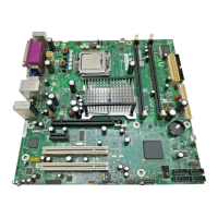
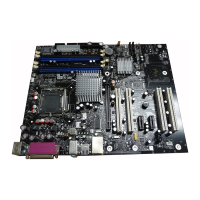
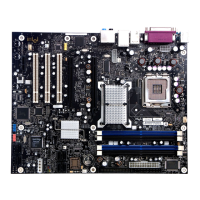
2.7.2.1 Chassis Fan Connectors
The board has two standard and one optional chassis fan connectors:
• Front chassis fan
• Rear chassis fan
• Auxiliary fan connector (optional)
Table 22 lists the signal names for the front and rear chassis fan connectors. Table 24 lists the
signal names for the auxiliary fan connector.
Table 22. Front and Rear Chassis Fan Connectors
Pin Signal Name
1 FAN_CONTROL
2 +12 V
3 FAN_TACH
Table 23. Auxiliary Fan Connector (Optional)
Pin Signal Name
1 Ground
2 +12 V
3 FAN_TACH
(Note)
4 FAN_CONTROL
Note: The tachometer output is not monitored by the hardware monitoring and fan control ASIC.
 Loading...