TruPortal Dual Door Interface Quick Reference 4 P/N 460802991B 26JAN12 en-US
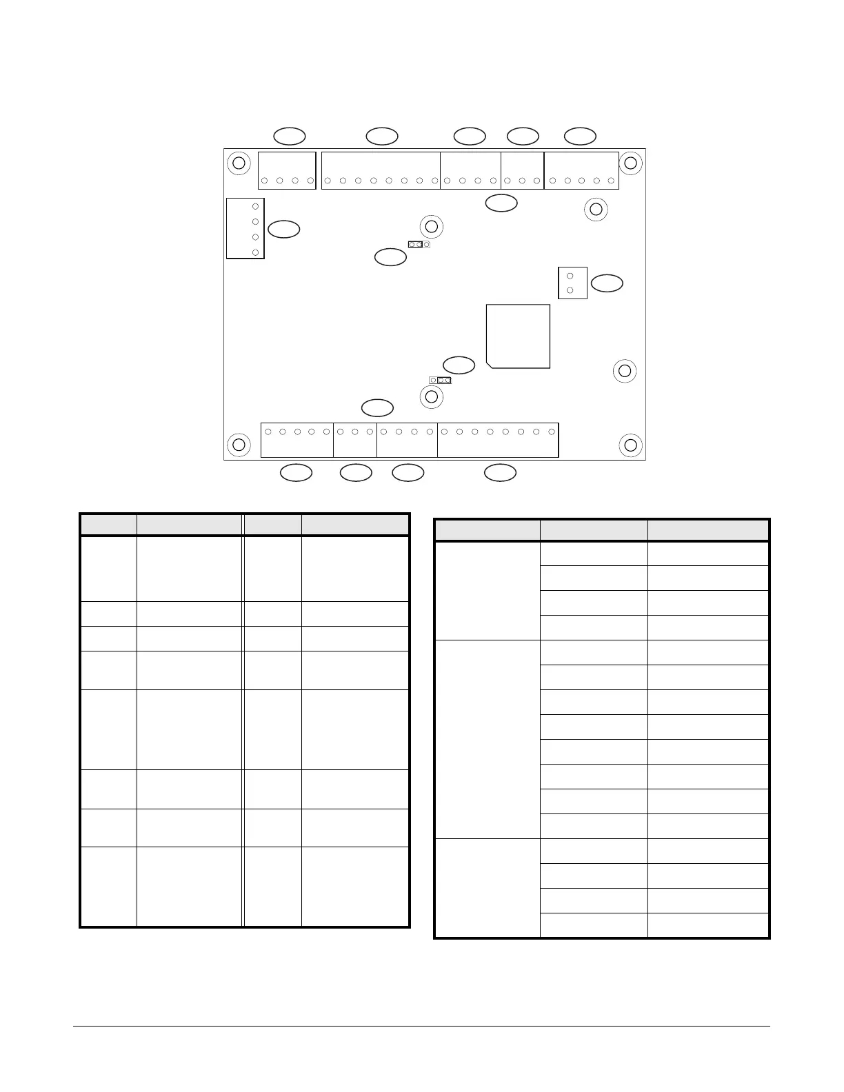
Dual Door Interface Module Pinouts
Callout Description Callout Description
1 TB1 (Module Bus;
wired from previous
device and to next
device)
9 TB9 (Input)
2 TB2 (Reader) 10 TB10 (Input)
3 TB3 (Input) 11 TB11 (Reader)
4 TB4 (Input) 12 Door 2 (one or two
readers)
5 TB5 (Unlock Relay
and Aux Relay, with
pins NC2, NO2, and
COM2 for Unlock
Relay)
13 Door 2 reader
voltage
6 TB6 (Module Bus) 14 Door 1 (one or two
readers)
7 Tamper 15 Door 2 reader
voltage
8 TB8 (Unlock Relay
and Aux Relay, with
pins NC2, NO2, and
COM2 for Unlock
Relay)
Terminal Block Pin Label Description
TB1 +12V (+) 12V - Red
A Data A - Green
B Data B - Yellow
0V (-) 0V - Black
TB2 5/12 (+) 5/12 VDC
GRN Green LED
RED/RXD Red LED
R1D1 R1 Data 1
R1D0 R1 Data 0
GND (-) 0V Signal Ground
R2D1 R2 Data 1
R2D0 R2 Data 0
TB3 DCNT Door Contact Input
GND COM/Shared
RTMP Reader Tamper
BUZ BUZ Out (-)
Figure 1: Dual door interface module
1 21231231 2 3 4
GND RTMP BUZ 5/12 GRN
RED/
RXD
GNDDCNTRTEGNDAUXNO2COM2 R1D1 R1D0 R2D1NC2COM1NO1 R2D0
0VBA
+5V
+5V
+12V
+12V
12 34 5 612
1234
+12V5/12 GRN
RED/
RXD
GNDR1D1 R1D0 R2D1 R2D0
12 34 5
6121234
GND RTMP BUZ
DCNT
1
2
3
R
T
E
GN
D
AUX
12123
NO2COM2NC2COM1NO1
0VBA
1234
+12V
5
41
32
10
9
6
8
7
15
14
13
12
11
 Loading...