Detailed Function Description
86
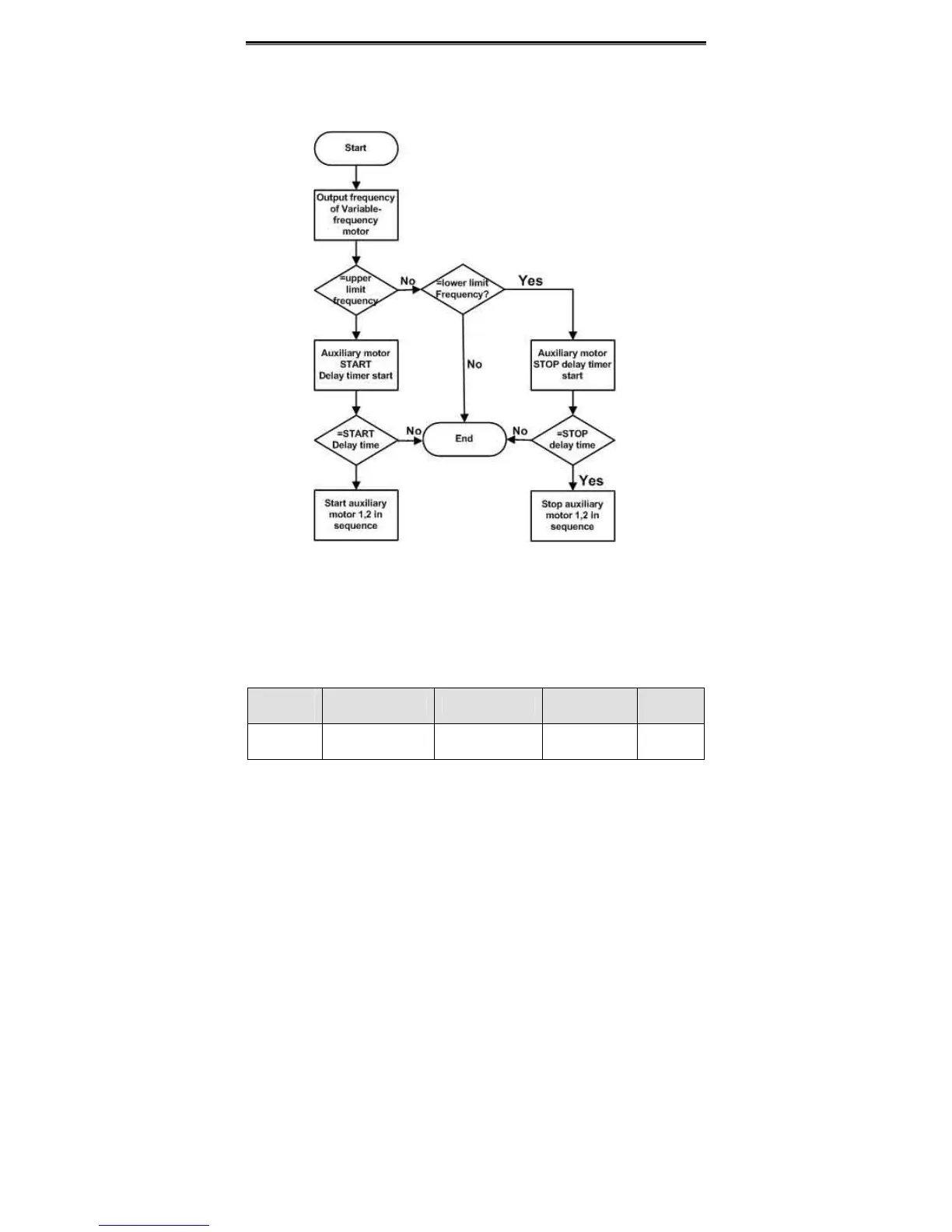
Above parameters are used to realize simple water supply control function which one
inverter drives three pumps (one variable-frequency pump and two power-frequency
pumps). The control logic is shown in the following figure.
Figure 6.26 Simple water-supply function logical diagram.
Notice:
z Delay time of start auxiliary motor and stop auxiliary motor are the same.
z PID control (P0.03=6) is necessary for simple water supply control.
z P1.14 should not be set to be 1.
Function
Code
Name Description Setting Range
Factory
Setting
P8.32
Brake threshold
voltage
320.0~750.0V 320.0~750.0 700.0V
When the DC bus voltage is greater than the value of P8.32, the inverter will start
dynamic braking.
 Loading...
