Wiring
19
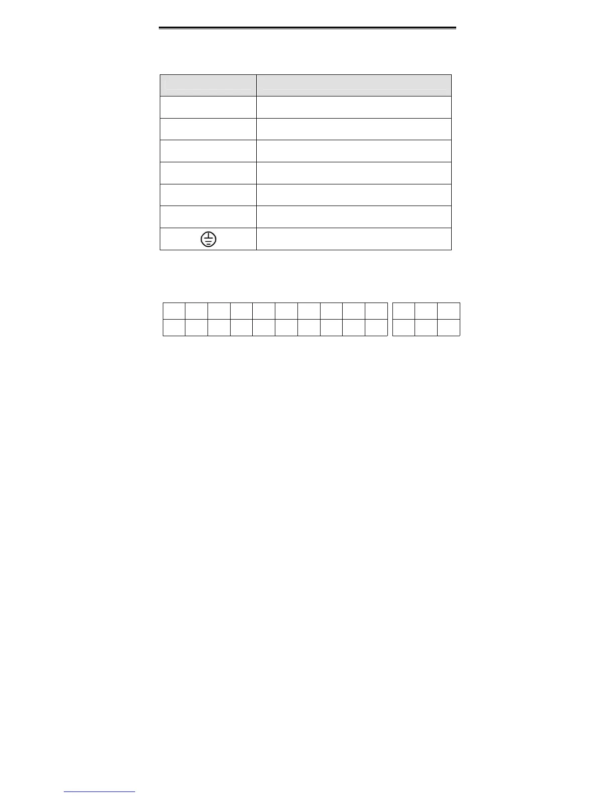
Main circuit terminal functions are summarized according to the terminal symbols in the
following table. Wire the terminal correctly for the desired purposes.
4.2.2 Control Circuit Terminals
GND
R01A
R02A
R01C
R01B
R02C
R02B
AI1
S2
S1
S5
S3
S4
HDI1
GND
COM
AI2
10V
+
PW
24V
+
COM
CME
Y1
AO1HDO
PE
Figure 4.7 Control circuit terminals.
Terminal Description
R、S、T
Terminals of 3 phase AC input
(+)、(-)
Spare terminals of external braking unit
(+)、PB
Spare terminals of external braking resistor
P1、(+)
Spare terminals of external DC reactor
(-)
Terminal of negative DC bus
U、V、W
Terminals of 3 phase AC output
Terminal of ground
 Loading...
