EasyManua.ls Logo

Iron Baltic ATV Series User Manual

Iron Baltic ATV Series
44 pages
To Next Page IconTo Next Page
To Previous Page IconTo Previous Page
Page #9 background imageLoading...
Page #9 background image
8
FLAIL MOWER is designed to give safe and dependable service if operated according to instructions
and intended use. Read and understand this manual before operating the mower, as failure to do so
could result in personal injury or equipment damage.
When used with and ATV or compact tractor, ear defenders should be worn. Under
normal working conditions a noise level of 83 decibels would be usual, in the case protection
is advised.
The above decals should be located on your Flail Mower. If any of the above decals are not
located on your Mower or are damaged in damaged in any way contact for some replacement decals
before use.
5
OPERAT
ING INSTRUCTIONS
Question and Answer IconNeed help?

Do you have a question about the Iron Baltic ATV Series and is the answer not in the manual?

Iron Baltic ATV Series Specifications

General IconGeneral
BrandIron Baltic
ModelATV Series
CategoryLawn Mower
LanguageEnglish

Summary

Introduction

Safety Do Not Instructions

DO NOT Operate the mower without all the correct guards fitted

Ensures all safety guards are securely attached before operating the mower.

DO NOT Touch any moving or rotating parts, during working conditions

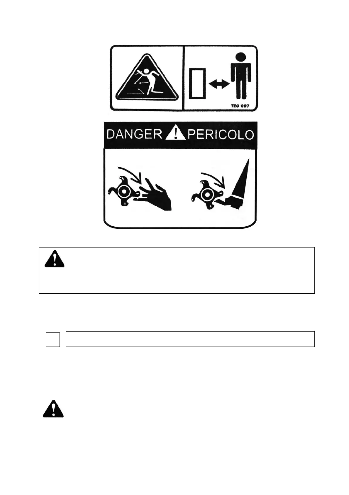
Never contact rotating components while the mower is in operation to prevent severe injury.

DO NOT Try to remove blockages while the engine is running

Ensure the engine is stopped and rotor has stopped before clearing blockages.

DO NOT Operate the mower without suitable ear and eye protection

Always wear appropriate personal protective equipment (PPE) for hearing and vision.

Safety Do Instructions

DO Ensure all spectators are a safe distance away when operating

Maintain a safe distance for all bystanders during mower operation.

DO Carry out regular servicing and checks before use

Perform routine maintenance and pre-operation checks for safety and reliability.

DO Reduce speeds when working on hillsides or rough terrain

Operate at reduced speeds on uneven ground or slopes for better control.

DO Keep hands and feet away from rotating blades

Maintain a safe distance for hands and feet from the mower's rotating blades.

Instruction and Warning Decals

WARNING To prevent Serious Injury or Death

Crucial warning about operating the machine only after reading and understanding the manual.

ATTENTION Your responsibilities before operating this machine are:

Key user responsibilities including reading manuals, training, and ensuring guards are fitted.

Operating Instructions Overview

DANGER PERICOLO Decals

Location and importance of danger and hazard warning decals on the mower.

When used with and ATV or compact tractor, ear defenders should be worn.

Wear ear defenders when operating with an ATV or tractor due to noise levels.

Initial Check Procedures

Make sure that all nuts, bolts and fittings are securely fixed

Verify all nuts, bolts, and fittings are secure and packaging material is removed.

Check there is oil in the engine and petrol in the tank

Ensure the engine has sufficient oil and the fuel tank is filled with petrol.

Drawbar Adjustment

TO ADJUST Lengthen the link to lower the front of the deck

Adjust the drawbar link to ensure the cutting deck is horizontal for efficient cutting.

Mower Cutting Height Adjustment

CUTTING HEIGHT ADJUSTMENT: Turn the handle to raise or lower

Use the screw jack handle to adjust the cutting deck to the desired height.

Starting the Engine

READ AND UNDERSTAND THE ENGINE OPERATORS MANUAL BEFORE USE

Crucial instruction to read and understand the engine manual before starting.

Observe all safety precautions; keep hands and feet away from rotor

Follow safety rules, keeping hands and feet clear of moving parts.

NOTE If the throttle is altered to increase the engine R.P.M

Warning against altering RPM beyond limits; it voids warranty and affects performance.

Electric Start Operation

Push button electric start engine options can be supplied if required.

Information on electric start options and connection to ATV power.

Forward Speed Control

NORMAL FORWARD SPEED (1 kph - very heavy use - 10 kph very light use)

Guidance on optimal forward speeds based on cutting conditions and engine load.

NOTE When moving from normal working conditions to heavier cutting

Instruction to slow down immediately when encountering heavy cutting conditions.

FAILURE TO DO THIS WILL RESULT IN CLUTCH SLIP

Warning about severe damage to clutch and belts if engine is overloaded.

Stopping the Mower Procedure

run the machine at half working speed in a stationary position, for at least 4 minutes

Cool down procedure: run at half speed for 4 minutes after heavy use.

Show caution to hot parts e.g. engine exhaust, belts etc

Be cautious of hot components like the exhaust and belts after stopping.

When the mower has cooled down (Min 1hr after last used) ensure all grass has been removed

Clean debris from cooling fins, belts, and rotors after the mower has cooled down.

Transport Position

raise the deck to the highest position (Transport position)

Raise the cutting deck to its highest setting for safe transport.

Please note the AT Flail Mower is not road legal

Important notice: The mower is not street legal and must not be used on public roads.

Anti-Scalping Roller and Side Skids

The main purpose of the anti scalping roller is to prevent damage.

The anti-scalping roller prevents ground damage by taking mower weight on uneven terrain.

However, if the mover is used in rough conditions or regularly in heavy crops

Adjust roller and skids lower for rough conditions to increase ground clearance.

Maintenance Overview

Maintenance Schedule

Overview of maintenance tasks required hourly, daily, weekly, and seasonally.

6.1 ENGINE

Refer to the engine manual for specific engine servicing and maintenance procedures.

6.2 EXCESS CROP BUILD UP

Instructions for removing accumulated crop matter to prevent heat build-up and fires.

Visual Check

Make a visual check around the mower, check for missing / loose parts

Inspect the mower for loose, missing, or damaged components and repair as needed.

Tyre Pressure Check

DO NOT exceed recommended type pressures

Warning to not exceed the maximum recommended tyre inflation pressures.

Rotor Bearing Inspection

Rotate rotor shaft by hand and feel for any roughness

Check rotor bearings for roughness or play by rotating the shaft manually.

Wheel Bearing Inspection

Jack one side of the mower body up, so the wheel is just off the ground.

Lift the mower to inspect wheel bearings for play and alignment.

Greasing Coupling and Bush Wear

Check coupling for signs of damage or wear, swivel the coupling 360 degrees

Inspect the 50mm coupling and bushes for wear or damage and grease regularly.

General Inspection

Check the mower to ensure all fasteners are tight and all safety guards / chains are intact

Verify all fasteners, guards, and chains are secure and in good condition.

Rotor Flail Maintenance

When breaking or losing a knife, it is important to replace it immediately.

Replace broken or lost flail knives promptly to prevent unbalancing.

Replacing or reversing the knives follows this simple procedure:

Step-by-step guide for replacing or reversing rotor flail knives.

Never use cracked or repaired shackles when replacing knives.

Warning against using damaged or repaired shackles; replace with new parts.

Changing Drive Belts

Check belts wear and tension regularly.

Regularly inspect belts for wear and ensure correct tension to prevent premature wear.

Belts changing instructions;

Detailed instructions on how to safely change the mower drive belts.

Remove cover off the belts housing.

First step: remove the protective cover from the belts housing.

Release the locknut of the tensioner arm.

Loosen the locknut on the tensioner arm to adjust belt tension.

Belt Replacement Steps

Put / turn the belts on to the wheels one at a time.

Install new belts onto the pulleys one by one.

Tighten the belts by turning the tensioning pulley arm back until belts tightened

Adjust belt tension by turning the pulley arm until 10-15mm compression is achieved.

Specifications / measurement of the belts used can be found on the belts housing cover

Belt specifications are available on the housing cover or the manual's first page.

Belts Housing Cover Installation

7. Fit the belts housing cover.

Reattach the belts housing cover after completing belt replacement.

Clutch Replacement

Worn clutch will cause premature wear of the belts!

Warning: A worn clutch can lead to premature belt wear; check friction pads regularly.

Clutch replacing instructions;

Step-by-step guide for removing and replacing the clutch assembly.

Remove the belts (see pt 6.10, step 1-4).

First, remove the drive belts following the procedure in section 6.10.

Remove the locknut of the clutch assembly.

Loosen and remove the locknut securing the clutch assembly.

Pull the clutch assembly off the engine crankshaft

Carefully remove the clutch assembly from the engine crankshaft, using tools if necessary.

Clutch Re-installation

5. Re-install the belts (see pt 6.10, steps 4-7).

Reinstall the drive belts according to the steps outlined in section 6.10.

For repairs beyond the minor adjustments listed above, contact your dealer.

For complex repairs, consult your authorized dealer for assistance.

Spare Parts List

ATV Flail Mower Assembly

Exploded view diagram of the ATV Flail Mower components.

Traction Assembly Components

Arm weldment

Component: Arm weldment.

Bracket for traction

Component: Bracket for traction.

Hook for traction

Component: Hook for traction.

Axle sleeve

Component: Axle sleeve.

Shaft tube for traction

Component: Shaft tube for traction.

Lifting assembly

Component: Lifting assembly.

Axle

Component: Axle.

Split pin 5X32

Component: Split pin 5X32.

Wheel Partment Assembly Components

Oil cup M6

Component: Oil cup M6.

Mut N12

Component: Mut N12.

Plain washer 12

Component: Plain washer 12.

Protection casing weldment

Component: Protection casing weldment.

Bolt M12x35

Component: Bolt M12x35.

Handle

Component: Handle.

Bearing 61904

Component: Bearing 61904.

Bearing seat

Component: Bearing seat.

Bearing 51104

Component: Bearing 51104.

Screw M8x30

Component: Screw M8x30.

Adjusting screw

Component: Adjusting screw.

Sheath for handle

Component: Sheath for handle.

Cover for tyre

Component: Cover for tyre.

Bearing 80205

Component: Bearing 80205.

Tyre

Component: Tyre.

Rubbber cover

Component: Rubber cover.

Supporting bracket for tyre

Component: Supporting bracket for tyre.

Nut M10

Component: Nut M10.

Plain washer 10

Component: Plain washer 10.

Blot M10x65

Component: Bolt M10x65.

Tension spring

Component: Tension spring.

Bolt M12x70

Component: Bolt M12x70.

Adjusting coil

Component: Adjusting coil.

Crossbeam weldment

Component: Crossbeam weldment.