14
I
I
I
I
I
I
.
.
M
M
e
e
c
c
h
h
a
a
n
n
i
i
c
c
a
a
l
l
i
i
n
n
s
s
t
t
a
a
l
l
l
l
a
a
t
t
i
i
o
o
n
n
o
o
f
f
t
t
h
h
e
e
v
v
a
a
r
r
i
i
o
o
u
u
s
s
v
v
e
e
r
r
s
s
i
i
o
o
n
n
s
s
Please ensure you read the paragraph: Special Specifications for use in Potentially Explosive
Atmospheres in Accordance with European Directive ATEX 94/9/EC
See Appendix 1 for general installation instructions.
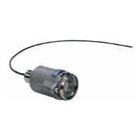
1. OLC20 and OLCT20
- See Figure 01 (at the beginning of this manual).
Note: The threaded outlet from the body can be used to attach the OLC20 detector or the
OLCT20 transmitter to its mounting (box, case, etc.).
2. OLC20D and OLCT20D (remote version)
- See Figures 02 and 03 (at the beginning of this manual).
3. OLCT 40
See the beginning of this manual:
- Figure 04 for dimensions,
- Figure 05 for attachment of the main housing.
4. OLCT 40D (remote version)
See the beginning of this manual:
- Figure 06 for dimensions,
- Figure 03 for attachment of the remote cell.
I
I
V
V
.
.
W
W
i
i
r
r
i
i
n
n
g
g
o
o
f
f
t
t
h
h
e
e
v
v
a
a
r
r
i
i
o
o
u
u
s
s
v
v
e
e
r
r
s
s
i
i
o
o
n
n
s
s
Please ensure you read the paragraph: Special Specifications for use in Potentially Explosive
Atmospheres in Accordance with European Directive ATEX 94/9/EC
1. 3-Wire versions
- - See Figure 07 (at the beginning of this manual)
2 2-wire versions
- - See Figure 08 (at the beginning of this manual)
3. 2-wire Intrinsic Safety versions
- See figure 09 (at the beginning of the manual)

 Loading...