Functions and Characteristics
Copyright © ITECH Electronics Co., Ltd. 24
QUES bit is 1, FLT outputs low level. When QUES bit is 0, FLT outputs high level.
OPER: The output level of FLT changes along with the state of OPER bit.
ESB: The output level of FLT changes along with the state of ESB bit.
RQS: The output level of FLT changes along with the state of RQS bit.
OFF: The output level of FLT remains high.
When “Port Mode” in menu is set with “DIGITAL I/O”, FLT port becomes output port
to control the output status by communication order.
IT6150 4 pin connector in rear panel
GND, TRIN: Trigger port
-, +: Remote sense port
3.8 Milliohm Meter
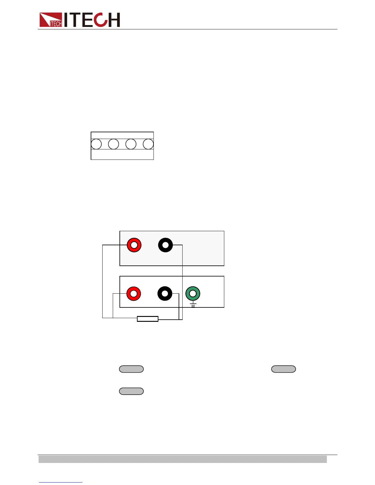
SOURCE METER can measure resistant value accurately and the biggest
resistance it can measure is 1kΩ. In order to protect the resistor, please select the
power range of the resistor before you measure it. Wiring diagram as follows:
+
-
+
OUTPUT
-
5 ½ DVM
R
+
-
+
OUTPUT
-
5 ½ DVM
R
+
-
+
OUTPUT
-
5 ½ DVM
R
There are 3 ranges to be chosen: 0.1W、1W、10W.
The accuracy of the measurement is <1%, the higher range you select, the more
accurate result you can get.
Option:
1. Press
+V/m
(if VFD displays**.**V, press
+V/m
), set
m:
**, you can measure resistance value.
2. Press
+0.1W /1W /10W, you can set different range of milliohm meter.
3.9 Voltage Meter
Wiring diagram as follows:
 Loading...