Quick Start
Copyright © Itech Electronic Co., Ltd. 9
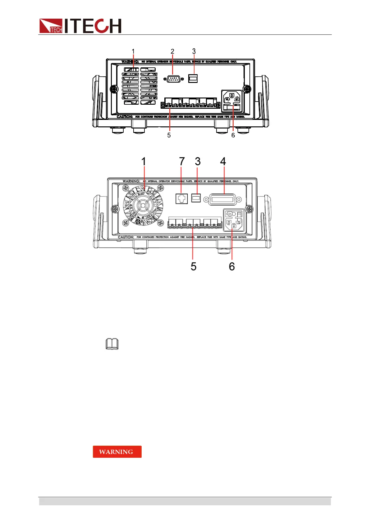
The rear panel of IT6322C/IT6332C/IT6333C is shown in the next figure.
1. Cooling window
2. RS232 communication interface
3. USB communication interface
4. GPIB communication interface
5. Remote measurement terminals and output terminals
6. AC power input socket and fuse
7. LAN communication interface
Note
The 110V/220V power switch is at the bottom of the instrument.
Please check the switch position before powering on to avoid burning
the instrument.
2.6 Power-on Selftest
A successful selftest indicates that the purchased power product meets
delivery standards and is available for normal usage.
Before operation, please confirm that you have fully understood the safety
instructions.
To avoid burning out, be sure to confirm that power voltage matches with
supply voltage.
Be sure to connect the main power socket to the power outlet of
protective grounding. Do not use terminal board without protective
 Loading...