56
FOR THE INSTALLER
Connect the heat pump to a heating system with bypass
A connection with a bypass is necessary when a minimum fl ow cannot be guaranteed during the entire year.
Application: The principle is based on fl oating condensing in the heat pump (curve control) and additional heat from an
electric cassette. The built-in control unit controls the heat pump using the outdoor sensor T2 (GT2) and the return sensor
T1 (GT1) according to the outdoor compensated control curve. When the heat pump is unable to meet the heating require-
ments, the electric cassette starts automatically and together with the heat pump provides the required temperature. The
heating of hot water is given priority over the heating of the heating water. Hot water heating is controlled by the sensor T3
(GT3), which is located in the hot water cylinder. When the water in the cylinder is heated, a three-way valve temporarily
disconnects heating radiator mode. When the water in the cylinder reaches the required temperature, heat is once more
supplied to the heating system.
The control unit can also control a second curve together with a mixing valve. The mixing valve curve must be set lower
than the heat curve for the rest of the heating system. This extra function is used, for example, in a fl oor heating system
that requires a lower temperature.
Connecting the sensors: External sensors T1 (GT1) and T2 (GT2) must always be connected. Sensor T3 (GT3) is
connected if the heat pump is to produce hot water. Sensor T4 (GT4) is only connected if a mixing valve curve is used.
Sensor T5 (GT5) is connected when the heat pump is to be infl uenced by a room sensor.
Accumulator tank: In systems where individual room temperature control is required, for example, with fl oor heating in
one of the rooms, an accumulator tank of 100-300 litres is recommended. This is suffi cient to ensure good operating times
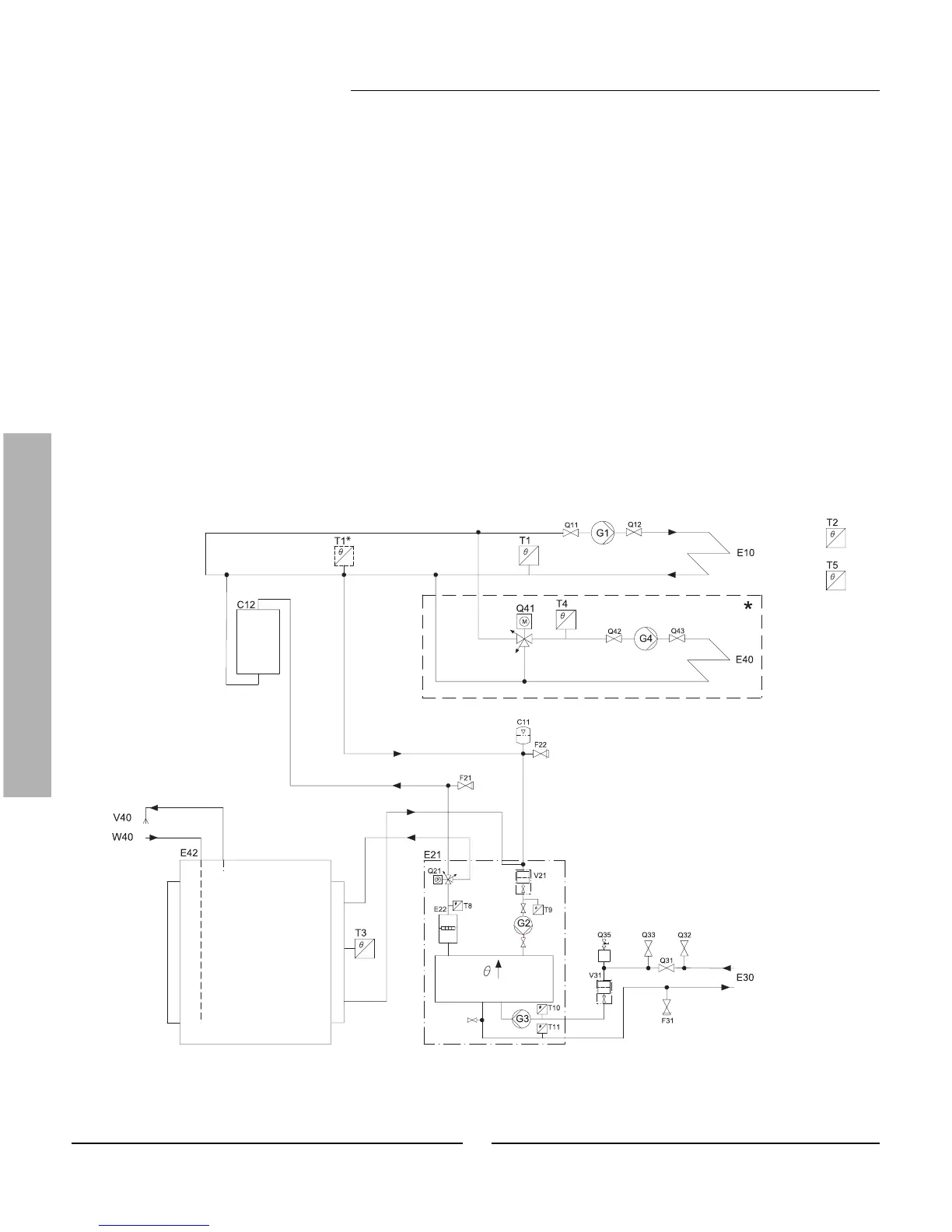
for the heat pump. T1 (GT1) should be installed according to T1* in the diagram below.
Heating system
C11: Expansion tank
E42: Hot water heater
F21: Safety valve
F22: Safety valve
F31: Safety valve
G1 (P1): Radiator pump
G2 (P2): Heat carrier pump
G3 (P3): Heat transfer fl uid pump
G4 (P4): Pump for mixed valve system
Q41: Mixing valve
V21: Filter Heating system
V31: Filter Heat transfer fl uid in
V40: Hot water
W40: Cold water
* Mixed heating system
There is a possibility to control a second
heating system with a mixing valve. This
is recommended when a combination of
radiators and a fl oor heating system is used.
Symbols according to ISO/FDIS 14617.
Letter codes according to IEC 61346-2.
This is a principal drawing.
Connecting the heat pump to the heating system
 Loading...


