Maintenance Manual for J2 Sedan
Electronic Control System
163
Section II Structural Principle and
Engine Control System
I. System
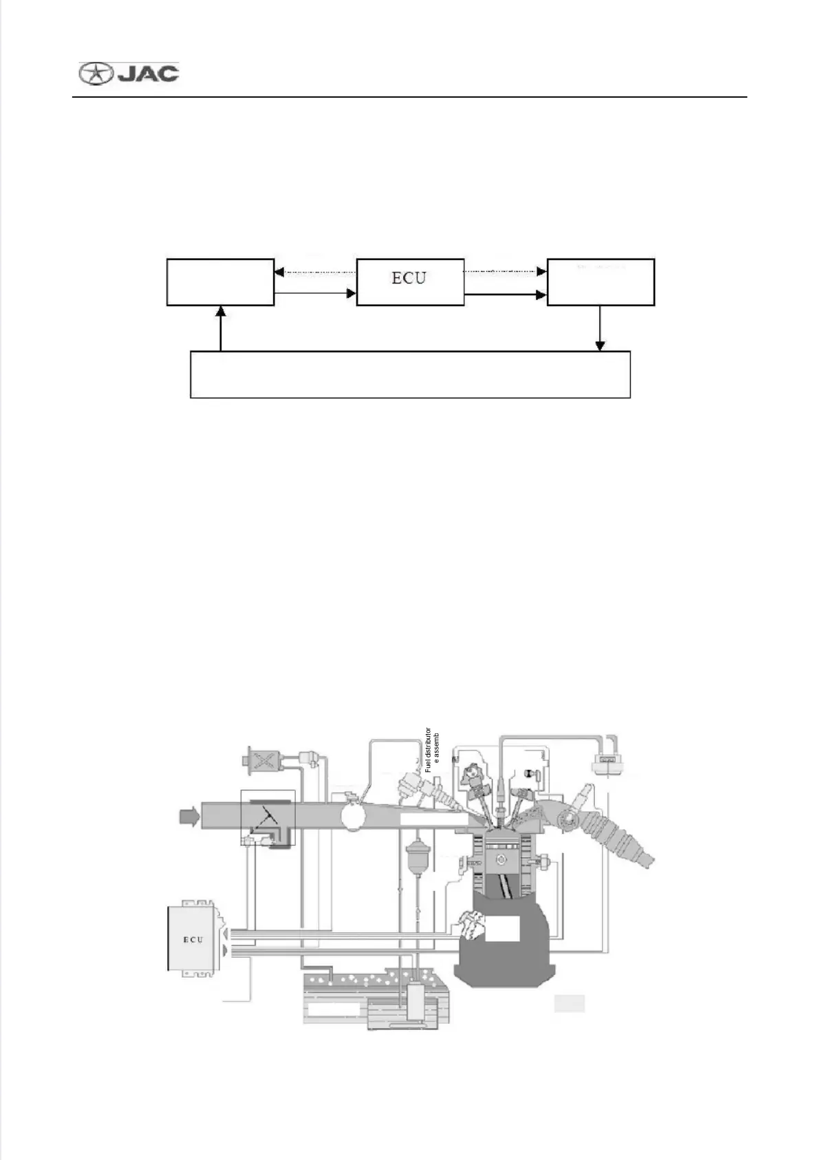
Generally, the engine management system is mainly composed of three parts, namely sensors,
micro-processor (ECU), and actuators, to control the intake volume, fuel injection amount, and ignition
advance angle during the running of the engine. The basic structure is shown in the figure below:
Basic Structure of Engine Control System
In the engine electronic control system, the sensors are functioned as input parts to measure all kinds of
physical signals (tempera
etc.) and convert to
ing electric signals, the ECU is
functioned to receive the input signals from sensors, calculate and process as per preset programs,
generate corresponding control signals, and output to power drive circuits, and the power drive circuits
execute different actions by driving corresponding actuators and control the engine to run as per preset
control strategy. At the same time, the malfunction diagnosis system of ECU monitors various
components and control functions in the system. Once a malfunction is detected and confirmed, the
system will save the malfunction code and activate the “Limp home” function. Upon the detection that
the malfunction is resolved, the system will resume to normal values.
The greatest characteristic in the electronic control system of the M7 engine is the adoption of
torque-based control strategy. The torque-based control strategy is mainly intended to link a great
amount of different control objectives. This is the sole method to integrate flexibly all kinds of functions
into different variants of ECU depending on the engine and vehicle models. The structural diagram of
the electronic control system is shown as below:
Engine
Actuators
Sensors
interface
sensor
sensor
Phase
Intake
sensor
Fuel tank
sensor
control valve
Carbon canister

 Loading...