Page 18
3.5 Temperature Sensors
1. Drill3/8"holeinpipebetweenlter
pumpandlterandinstalltheWater
Temperature Sensor per instructions
(make certain the o-ring is in place).
2. Install AirTemperatureSensor outside the
Power Center can, not in direct sunlight and
away from motors and other heat sources.
3. Install Solar Temperature Sensor
(optional) adjacent to solar panels.
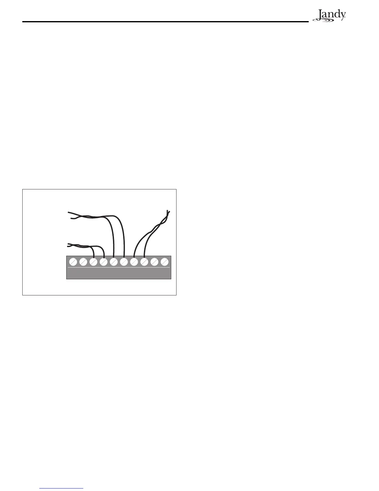
4. Run the wire to the Power Center, through
the low voltage raceway. Cut off excess
wire. Strip the wire jacket back 6", then
strip each wire ¼". Connect sensor wires to
the green, 10-pin terminal bar (see
Figure 17).
3.6 JandyValveActuators
NOTE Mount the JVAs according to the Jandy Valve
Actuator Installation and Operation Manual.
JVA cable is type SJW-A marked water resistant
class 3 cable and does not require conduit.
KnockoutsandHeycofittingsareprovidedinthe
Low Voltage Raceway.
1. Route the JVA wire to the Power Center.
2. Run the wire through the low voltage
raceway and plug the JVA connectors into
their proper sockets (see Section 6. Power
Center Wiring Diagram). Verify that the
JVA on the suction plumbing is connected
to the Intake JVA Socket, and the discharge
plumbing is connected to the Return JVA
Socket.
Figure 17. Temperature Sensor Wiring for a Pool/
Spa Combination
Water
Temperature
Sensor
Freeze/Air
Temperature
Sensor
Solar
Temperature
Sensor
Green 10-Pin Terminal Bar
NOTE Do not coil the JVA wires inside Power Center.
To shorten the wire, remove the JVA cover
and disconnect the wire. Shorten, strip, and
reconnect.
3. Foralternateplumbingcongurationsthe
JVA cam settings can be adjusted as needed.
See the Jandy Valve Actuator Installation
and Operation Manual, Cam Setting Chart
for proper settings.
3.7 PDATransceiverJ-boxInstallation
Installation Considerations. The transceivers will
transmit through walls and around corners. Steel
framing, aluminum siding, wrought iron, cyclone
fences, leaded glass, and other 900 MHz frequency
items may inhibit/prevent communication between
the AquaLink RS PDA Handheld Remote and the
Power Center. The transceivers do not require
line of sight to communicate. To optimize
communication, install transceivers in a location
that minimizes interference.
3.7.1 OutdoorTransceiverJ-boxInstallation
1. Turn off all power to the Power Center.
2. Mount the Outdoor Transceiver J-box at
least 6' above the ground and at least 8'
from an air blower (see Figure 18).
NOTE To improve performance of the transceiver,
mount the J-box more than 6' above the ground.
3. Open the door to the Power Center and
remove the dead panel.
4. Feed the four conductor wire into the Power
Center through the low voltage raceway.
5. Cut off the excess wire. Strip the jacket
back 6" and strip the individual wires
approximately ¼". Connect the four
conductor wire to the red terminal bar on
the Power Center PCB.
6. Install the dead panel to the Power Center
and restore all power.
 Loading...