STM809/810/811/812
4/18
SUMMARY DESCRIPTION
The STM809/810/811/812 MICROPROCESSOR
RESET Circuits are low-power supervisory devic-
es used to monitor power supplies. They perform
a single function: asserting a reset signal whenev-
er the V
CC
supply voltage drops below a preset
value and keeping it asserted until V
CC
has risen
above the preset threshold for a minimum period
of time (t
rec
). The STM811/812 also provide a
push-button reset input (MR
).
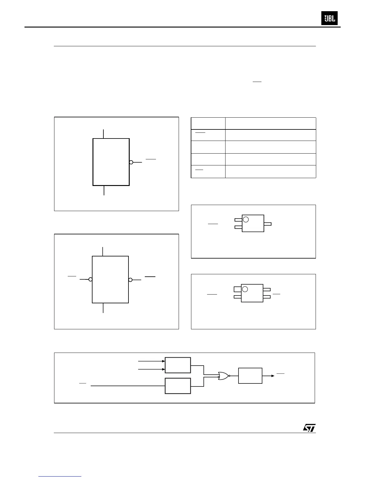
Figure 2. Logic Diagram (STM809/810)
Note: 1. For STM810
Figure 3. Logic Diagram (STM811/812)
Note: 1. For STM812
Table 2. Signal Names
Note: 1. STM810/812 only
2. STM811/812 only
Figure 4. SOT23-3 Connections
Figure 5. SOT143-4 Connections
Figure 6. Block Diagram
Note: 1. STM811/812 only
2. RST for STM810/812
AI07832
V
CC
STM809/810
V
SS
RST (RST)
(1)
AI07831
V
CC
STM811/812
V
SS
RST (RST)
(1)
MR
V
SS
Ground
RST
Active-Low RESET Output
RST
(1)
Active-High RESET Output
V
CC
Supply Voltage
MR
(2)
Manual Reset Input
AI07833
2
3
1
RST (RST)
V
SS
(For STM810)
V
CC
AI07834
2
4
3
1
RST (RST)
V
SS
(For STM812)
V
CC
MR
AI07835
COMPARE
V
RST
V
CC
DEBOUNCE
t
rec
Generator
MR
(1)
RST
(2)
ES250PW
 Loading...