Do you have a question about the JBL GTO 24001 and is the answer not in the manual?
Specifies power output, signal-to-noise ratio, and frequency response.
Details input impedance, sensitivity, and control features like bass boost.
Covers voltage range, current draw, turn-on delay, and protection mechanisms.
Lists all parts included in the amplifier's packaging and accessories.
General safety advice and considerations before installation.
Guidance on correctly wiring the amplifier's power, ground, and speakers.
Instructions for setting input levels, crossover, and other controls.
Description of the Power On and Protect LEDs.
Troubleshooting for no power or no sound from speakers.
Addressing distortion and engine noise in the audio output.
Resolving overheating shutdowns and protection mode errors.
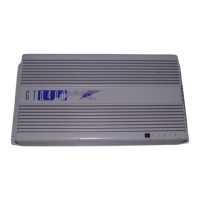
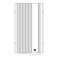
Visual breakdown of the amplifier's components and assembly.
Detailed list of all part numbers and their quantities.
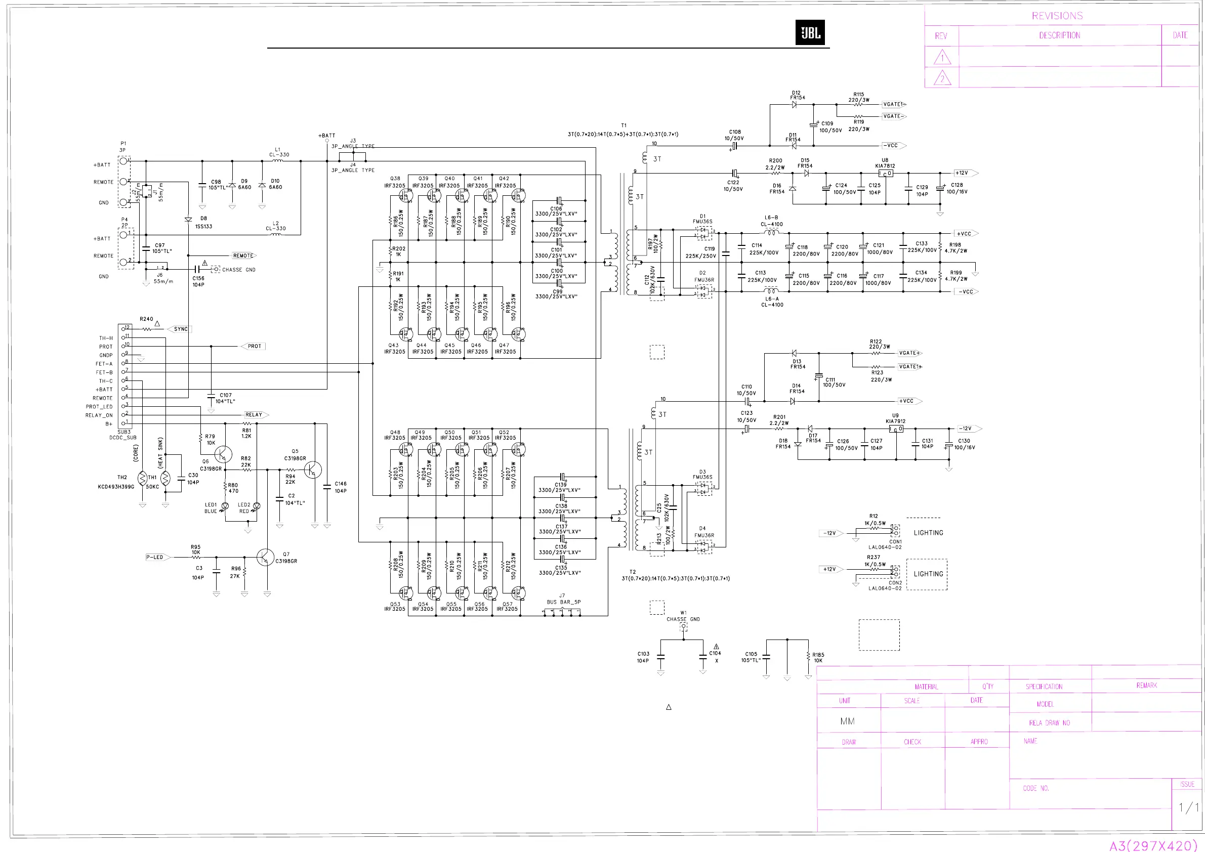
Illustrates the internal signal path and power supply stages.
Shows signal entry/exit, controls, and protection circuits.
Lists resistors, capacitors, and semiconductors for the main PCB.
Details components for driver, PWM, and Badge LED PCBs.
Visual representation of component placement on the main PCB.
Visual guide showing component placement on the Drive PCB.
Visual layout of components on the DCDC printed circuit board.
Description, features, and diagrams for the comparator IC.
Description, features, and pinouts for the counter IC.
Overview of the transconductance amplifier's capabilities and pin configuration.
Lists common transistors, MOSFETs, diodes, and regulators with their pinouts.
Diagrams for power input, regulation, and distribution circuits.
Schematics for input, filtering, bass boost, and remote control.
Diagrams of the final amplification and protection stages.
Schematics for bias adjustments and voltage control circuits.