12
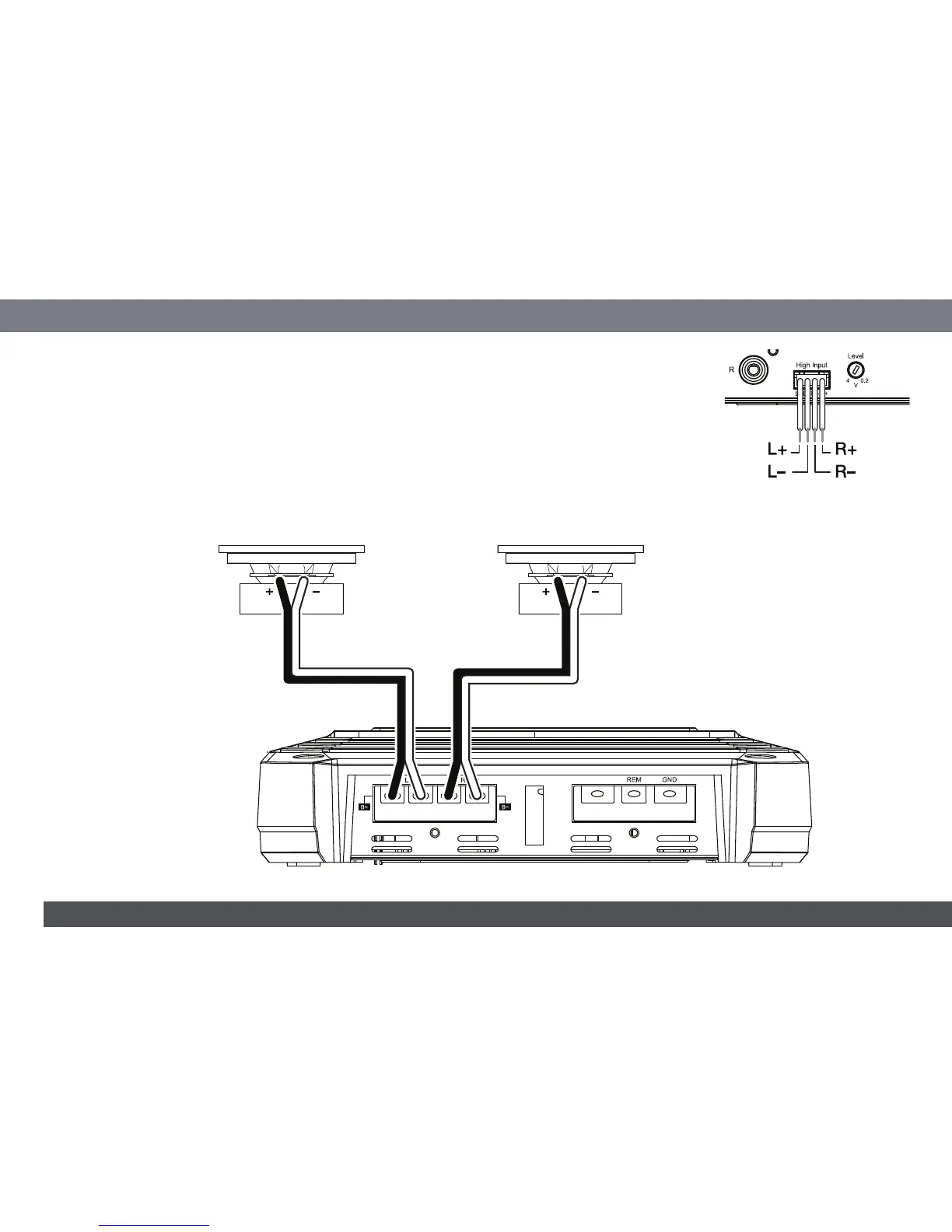
USING THE SPEAKER-LEVEL INPUTS
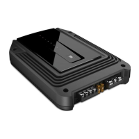
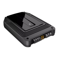
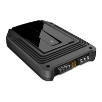
If your source unit doesn't have line-level outputs you can use the included speaker-level input harness to connect
the amplifier to the source unit's speaker outputs. From left to right, the conductors are: L+, L–, R–, R+ (see the
illustration to the right). The speaker-level connectors on all GX-series amp models follow this wiring configuration.
Follow the instructions in the previous sections, substituting the speaker-level connectors for the line-level
connectors.
GX-A602 SPEAKER CONNECTIONS; 2-CHANNEL OPERATION
Minimum speaker impedance: 2 ohms (each)
Connect the left and right speakers to the FL and FR (+) and (–) terminals.
Fuse 25A
+12V
Speaker
Front Left Speaker Front Right Speaker
 Loading...