21
LOW FREQUENCY PROCESSING
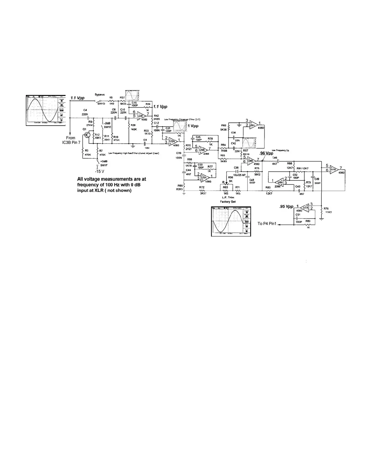
This is the processing circuitry for the low frequency spectrum. We are interested in this
circuit, shown above, because it provides the signal path that will discriminate the low frequency
component from the composite signal and filters that component out by actively rejecting high
frequency signals above the high critical frequency.
This circuit is located on the input printed circuit board and is instituted after the isolation buffer
integrated circuit, U3. The signal then enters the operational amplifier U2B where the signal is
contoured +/- 2dB by the user selectable DIP switches SW1B and SW1F. The MOSFET
detector Q1 performs this additive or subtractive operation in conjunction with U2B.Integrated
circuit U2A forms a second order low pass filter while U5 and U6 form band-pass filters offset
by the low frequency trimming resistor, R63.
Input 1.1
V
Out
ut=. 95 V
 Loading...