11
Dolby Pro-Logic
Ò
Surround Processor/CD Player/Tuner SOURCE
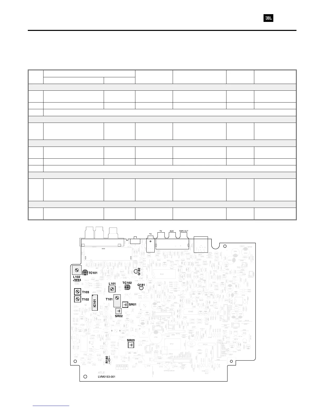
ADJUSTMENT PROCEDURE
Test Conditions
AM
(Amplitude Modulation)
Function.......................................................................AM
Input Level ............................................74dB/m (5mV/m)
Generator...................................Modulation 30%, 400Hz
Test Condition
FM
(Frequency Modulation)
Function.......................................................................FM
Input Level ................................................60dB/m (1mV)
Generator .................................Deviation 22.5kHz, 1kHz
Step
Signal or Sweep Generator
Reception
Frequency
Output Indicator
Connection
Adjustment Adjust For
Connection Frequency
AM TUNING VOLTAGE
1 No Signal 1710kHz
DC Digital Voltmeter
JW84
TC102 10.5+/-0.1V
2 No Signal 520kHz Same as Step 1 L101 1.2+/-0.1V
3 Repeat Step 1 and 2 a few times
AM IF
4
AM Loop Antenna at a
distance of 24 inch (60cm)
from the IRT Loop
450kHz
Point of
noninterference
IF Sweep Generator
IC101 Pin 12
T101 Flax and Max
AM TRACKING
5 Same as Step 4 620kHz 620kHz
RF Sweep Generator
R180
L102 Max
6 Same as Step 4 1400kHz 1400kHz Same as Step 5 TC101 Max
7 Repeat Step 5 and 6 a few times
FM IF
8
To the FM antenna
terminals through a
matching transformer
10.7MHz
Point of
noninterference
IF Sweep Generator
IC101 Pin 12
T102
T103
Flat and Max
Check Voltage
Between
R109=0V+/-30mV
FM MPX
9 Same as Step 8 98.1MHz 98.1MHz
RF Generator
Q181, Q182 “C”
SR03 Max Separation
 Loading...