8
Dolby Pro-Logic
Ò
Surround Processor/CD Player/Tuner SOURCE
DISASSEMBLY PROCEDURE
1) Lay unit face down. Remove the 5 Phillips screws
holding the upper & lower case together; separate cases.
2) Remove as many molex connectors as necessary to
separate case halves; do not mix up connectors during
reassembly. Label if necessary.
TROUBLESHOOTING
PROBLEM SOLUTION DETAILS
DISPLAY BRIGHTNESS
UNEVEN
Cut out R364 & R367 on CONTROL
PCB
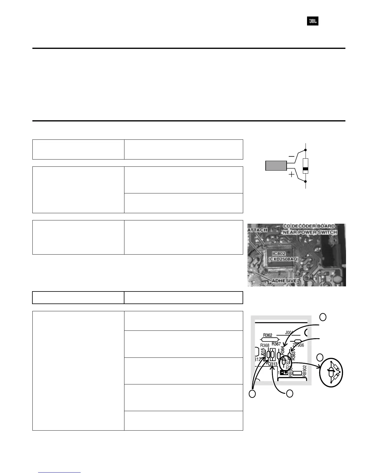
HUM IN CD MODE (1) Add 470uf 16v Cap. (PRE3952-471)
in parallel with ZD401 on MAIN PCB;
observe polarity (see drawing)
(2) Replace C472 (47uf 16v) with 470uf
16v cap. (PRE3952-471)
CD PLAY INTERMITTENT -
ONE CHANNEL DEAD
Add insulated jumper wire near IC802 on
CD DECODER PCB pin #67 and pad
exiting from corner of IC - ground. (see
illustration)
CD PLAY INTERMITTENT On MAIN PCB, cut out C721
CD PLAY INTERMITTENT -
DISPLAY BLINKING
On CONTROL PCB,
(1) Cut out jumper J015 and R368
(2) Replace existing part Q313 with
2SD882P NPN Transistor
(RHN0882-001)
(3) Solder 2 pcs. Diode IN41418
(RAD4148-001) in parallel with ZD301
(see illustration). Observe all polarities.
(4) R364 insert and solder a 2.4 ohm
resistor (or two 4.7 ohm [QAF0450-479]
in parallel)
(5) R363 insert and solder a 2.2K ohm
resistor (QAF0650-222)
470 f
16V
µ
ZD401
R362
J015
Q313
R363
R364
R367
R362
J015
Q313
R363
ZD301
ZD301
R364
R367
R368
1
RB901
RB902
J004
ZD906
R363 INSERT
2.2K / WΩ
1
6
R364 INSERT
2.4K / WΩ
1
4
DELETE
J015 & R368
Q313
INSERT
2SD882
1
2
3
4
 Loading...