15 - Engine
09 - Bedplate
00 - General
15 - 47 9813/9750-1 15 - 47
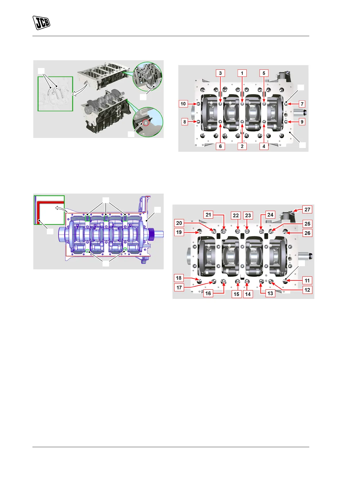
Figure 135.
D Lower bearing shells (x5)
F Shoulder half-rings (x2)
G Guide pins
6. Apply a 1.0mm (0.04in) thick bead of Loctite 5188
around the crankcase/bedplate mating face as
shown.
Figure 136.
H Crankcase
J Loctite 5188
K Oil feed holes
L Return oil grooves
7. Make sure that you do not block the oil feed holes
and the return oil grooves.
8. Assemble the bedplate to the crankcase. Make
sure that the guide pins on the crankcase are
engaged properly in the slots on the bedplate.
9. Note: The bedplate is heavy. Two people will be
required to lift and rotate the bedplate safely on
to the crankcase.
10. Install the main bearing bolts (x10).
11. Tighten the bolts to the correct torque value in
three stages. Strictly follow the torque sequence
shown.
Figure 137.
12. Install the bedplate peripheral bolts (x17).
13. Tighten the bolts to the correct torque value in
two stages. Strictly follow the torque sequence
shown.
Figure 138.
Important: If the parts have not been tightened to the
correct torque value within the maximum 15min time
period, then the parts must be separated, thoroughly
cleaned and fresh sealant should be applied.
After Installation
1. Check that the crankshaft can be freely rotated
by hand.
2. Measure the crankshaft end float. Make sure that
the end float is between 0.18mm (0.007in) and
0.38mm (0.015in).
3. Carry out the procedures listed in the 'Before
Removal' section in reverse order.
 Loading...