Section 1 - General Information
Standard Torque Settings
Hydraulic Connections
1 - 14 1 - 14
9803/4180-08
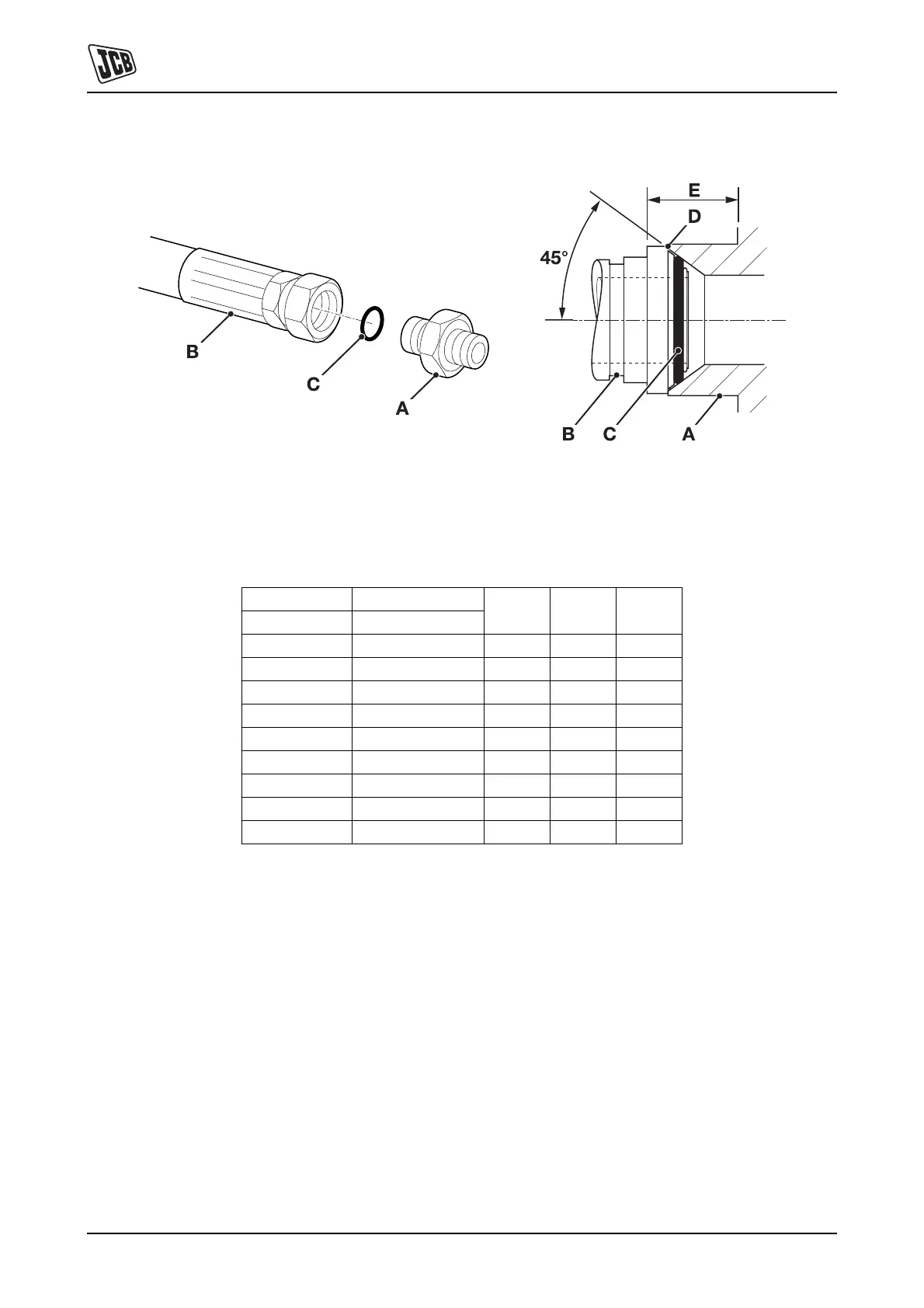
'Torque Stop' Hose System
Fig 9.
`Torque Stop' Hoses 9-B screwed into adaptors 9-A seal
onto an 'O' ring 9-C which is compressed into a 45° seat
machined in the face of the adaptor port. To prevent the 'O'
ring being damages as a result of over tightening, 'Torque
Stop' Hoses have an additional shoulder 9-D, which acts
as a physical stop.
Note: Minimum dimension 9-E fixed by shoulder 9-D.
Table 12. BSP `Torque Stop' Hose - Torque Settings
BSP Hose Size Hexagon (A/F)
Nm kgf m lbf ftin. mm
1/8 14.0 14.0 1.4 10.0
1/4 19.0 27.0 2.7 20.0
3/8 22.0 40.0 4.1 30.0
1/2 27.0 55.0 5.6 40.0
5/8 30.0 65.0 6.6 48.0
3/4 32.0 95.0 9.7 70.0
1 38.0 120.0 12.2 89.0
1 1/4 50.0 189.0 19.3 140.0
1 1/2 55.0 244.0 24.9 180.0

 Loading...