06 - Body and Framework
03 - Chassis
36 - Upper Crossmember
06 - 10 9813/5300-1 06 - 10
36 - Upper Crossmember
Remove and Install
Remove
1. Make the machine safe. Refer to (PIL 01-03).
2. Isolate the battery. Refer to (PIL 33-03).
3. Open the engine compartment cover. Refer to
(PIL 06-06).
4. Remove the rear road light electrical harness.
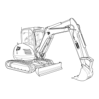
5. Disconnect the reverse alarm electrical
connector.
Figure 6.
A Electrical connector
6. Remove the bolts.
7. Support the upper crossmember with suitable
lifting equipment.
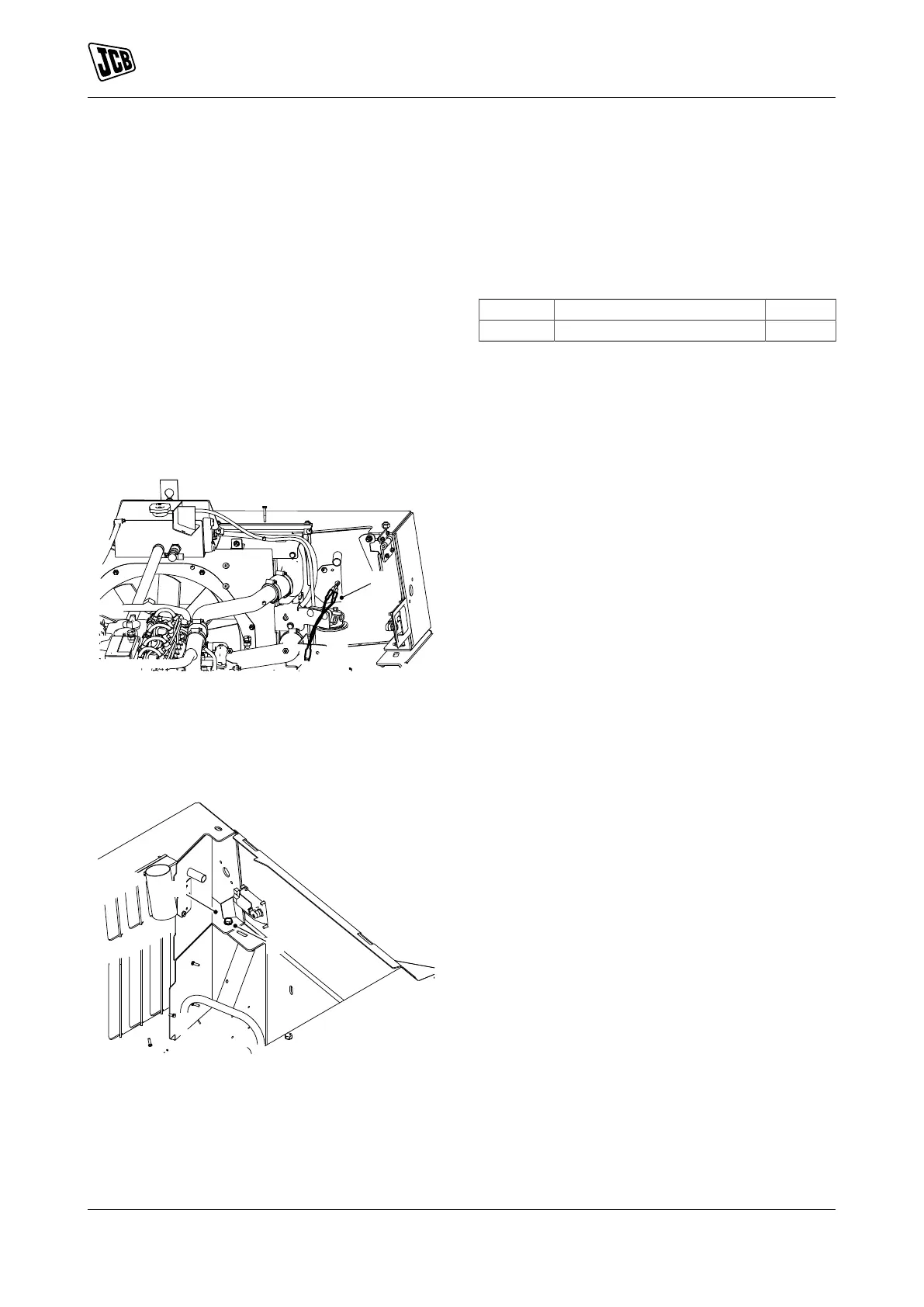
Figure 7.
B Upper crossmember
C Bolts
8. Remove the upper crossmember from the
machine.
Install
1. The installation procedure is the opposite of the
removal procedure. Additionally do the following
step.
2. Tighten the bolts to the correct torque value.
Table 2. Torque Values
Item Description Nm
C Bolts 230
 Loading...