EasyManua.ls Logo

JEFF ROWLAND 6 User Manual

JEFF ROWLAND 6
16 pages
To Next Page IconTo Next Page
To Previous Page IconTo Previous Page
Page #14 background image
Basic Troubleshooting
A
summary of fault conditions, their causes and remedies, are listed below.
The Model 6 Amplifiers can produce high power levels which, without well designed protection circuitry, could damage loudspeakers. Therefore, most fault
conditions which may occur during use will be indicated by the Model 6 reverting to a standby condition.
JRDG = Jeff Rowland Design Group, Inc.
Condition
FRONT PANEL STANDBY/POWER button lamp
does not illuminate after pressing, although the
Amplifier operates normally.
FRONT PANEL STANDBY/POWER button lamp
does not illuminate after pressing, and Amplifier
does not operate normally.
FRONT PANEL STANDBY/POWER button reverts
to standby condition during listening but can be
returned to operational condition.
Cause
Light bulb defective.
Incorrect power connections or AC MAINS
CIRCUIT BREAKER on Amplifier rear panel is
tripped.
Abnormal operation of Model 6 Amplifier internal
circuitry.
Excessive sub-sonic signals produced by source
components.
Severe clipping of Amplifier circuitry under
intermittent overload conditions.
Remedy
Remove STANDBY/POWER button from front panel
and replace bulb located under button. Use
replacement bulb kit and instructions supplied by
JRDG.
Review Installation/Rear Panel Power Connections
section. Reset CIRCUIT BREAKER on Amplifier rear
panel.
Consult dealer or JRDG.
Repair or replace source component (preamplifier).
Identify and correct abnormal conditions such as low
frequency rumble and/or acoustic feedback caused
by phono playback components (if applicable).
Reduce volume slightly or use higher efficiency
loudspeakers.
Question and Answer IconNeed help?

Do you have a question about the JEFF ROWLAND 6 and is the answer not in the manual?

JEFF ROWLAND 6 Specifications

General IconGeneral
DescriptionStereo Power Amplifier
Input Impedance100 kOhms
Gain26 dB
InputsXLR
OutputsBinding posts
Weight13.6 kg
Total Harmonic Distortion<0.03%

Summary

Introduction

Jeff Rowland Design Group Contact

Contact details for Jeff Rowland Design Group, Inc. including address and phone numbers.

Product Features

Input and Output Connectivity

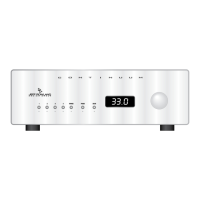
Features XLR balanced inputs, XLR/RCA adapters, and user-selectable gain/impedance.

Operational Characteristics

Includes remote switching, auto muting, and transient-free operation.

Design and Construction

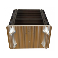
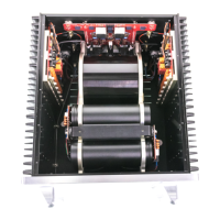
Highlights isolated circuitry, plug-in modules, and low-resonance chassis.

Initial Inspection

Included Contents

Lists auxiliary components included with the amplifier, such as cables and adapters.

Front & Rear Panel Function Controls

Front Panel Standby/Power Button

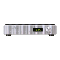
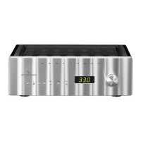
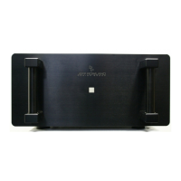
Explains the function and operation of the front panel standby/power button.

Rear Panel Input Impedance Switch

Details the user-selectable input impedance switch (18kΩ or 600Ω).

Rear Panel Overall Gain Switch

Details the user-selectable overall gain switch (26 dB or 32 dB).

Installation

Amplifier Placement and Cooling

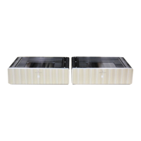
Guidance on locating amplifiers, ensuring adequate airflow, and vertical stacking.

Support System Installation

Details the use of spiked and compliant interface supports for coupling/decoupling.

Rear Panel Power Connections

Step-by-step instructions for making AC power connections.

Signal Connections

Interconnect Cable Installation

Instructions for installing XLR and RCA interconnect cables.

Loudspeaker Cable Connection

Guidance on connecting speaker cables to output terminals.

Remote Control Operation

Details the function of the remote connector for switching modes.

Output Terminal Warning

Important safety warning about output terminal electrical isolation.

Operation

Initial Power-On and Warm-up

Procedures for turning on amplifiers and recommended warm-up times.

Break-in Period

Discusses the initial break-in period for optimal performance.

Optimizing Performance

Recommendations for balanced input and low impedance for maximum performance.

Gain Structure Adjustment

How to use the OVERALL GAIN switch for system optimization.

Performance Specifications

Output and Bandwidth Specifications

Details output power, bandwidth, slew rate, THD, damping factor, and output current.

Input and Sensitivity Specifications

Covers input types, sensitivity, and common mode rejection ratio.

Power Consumption

Details standby and operating power consumption.

Physical and Shipping Specifications

Includes dimensions, weight, and shipping details.

Basic Troubleshooting

Standby/Power Button Issues

Addresses conditions where the standby/power button lamp does not illuminate or operate.

Amplifier Operational Faults

Covers issues like abnormal internal circuitry or reverting to standby mode.

AC Mains Circuit Breaker Trips

Troubleshooting for the AC mains circuit breaker switching off or not remaining on.

Noise Issues

Diagnoses and remedies for 50/60 Hz hum and high-frequency noise in loudspeakers.

Related product manuals