2 T2000 Series Low Voltage Fan Coil Thermostats Installation Instructions
Wallbox Mounting
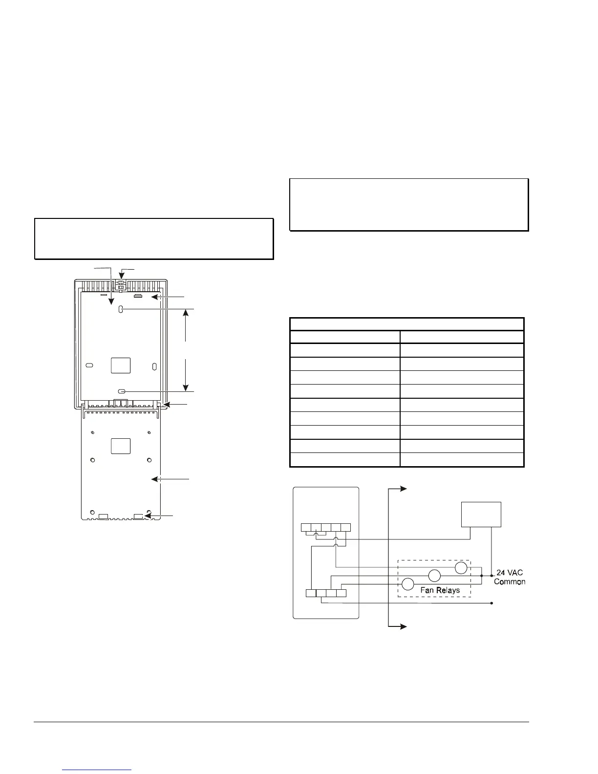
To mount the T2000-base to the to standard
U.S. wallbox, refer to Figure 1 and Figure 2 and:
1. Depress the PCB support latch, located above the
temperature setpoint switch in the upper
right-hand corner of the PCB support, and gently
pushing downward, swing the top of the PCB
support away from the unit.
Note: The PCB support will remain attached at the
bottom of the base, providing access to the mounting
and wiring holes.
IMPORTANT: Do not remove PCB from the PCB
support. Removing the PCB from the PCB support
voids the product warranty.
Retaining Screw
Base
PCB Support
(Back)
3.28
(83.4)
PCB Support
Base Hinge
PCB Support
Base Latch Notch
PCB Support
Base Latch
Figure 2: T2000xCx-0C0 Base with PCB Support
Mounting Dimensions
2. Pull the wiring through the square hole in the
base.
3. Fasten the base to the wallbox using the two
vertical holes and two No. 6 screws (not provided)
4. Pull the wiring through the square hole in the PCB
support and gently snap the PCB support to the
PCB Support Base Latch.
5. Proceed to the Wiring section for the correct
configuration for the application and unit.
Note: The factory-calibrated T2000 thermostat
requires no field adjustment. Do not attempt
recalibration.
6. Reposition the cover and tighten the retention
screw.
Wiring
IMPORTANT: Make all wiring connections in
accordance with local, national, and regional
regulations. Do not exceed the T2000 Series
thermostat’s electrical ratings.
Model T2000ACx-0C0
Wiring terminal designations appear in Table 1. Wiring
connections for typical T2000ACx applications appear
in Figure 3 and Figure 4.
Table 1: T2000ACx-0C0 Wiring Terminals
Model T2000ACx-0C0
Terminal Number Connection
1
Heating Valve +
2
Common
3
Heating Valve Common
4
High Fan Speed
5
Cooling Valve Common
6
Low Fan Speed
7
Medium Fan Speed
8
24 VAC Power
9
Cooling Valve
24 VAC
All Wiring to be
Supplied by Installers
System:
HEAT-OFF-COOL
Fan:
HIGH-MED-LOW
3
45
12
LOW
HIGH
MED
6
7
8
9
HEAT (H)/
COOL (C)
Valve
H
L
M
Figure 3: Wiring the T2000ACx-0C0 for
Heating/Cooling Only: 2-Pipe System
with 3-Speed Fan Control
 Loading...