T2000 Series Low Voltage Fan Coil Thermostats Installation Instructions 3
24 VAC
System:
HEAT-OFF-COOL
Fan:
HIGH-MED-LOW
3
45
12
COOL
(C)
Valve
HEAT
(H)
Valve
LOW
HIGH
MED
6
7
8
9
All Wiring to be
Supplied by Installers
H
L
M
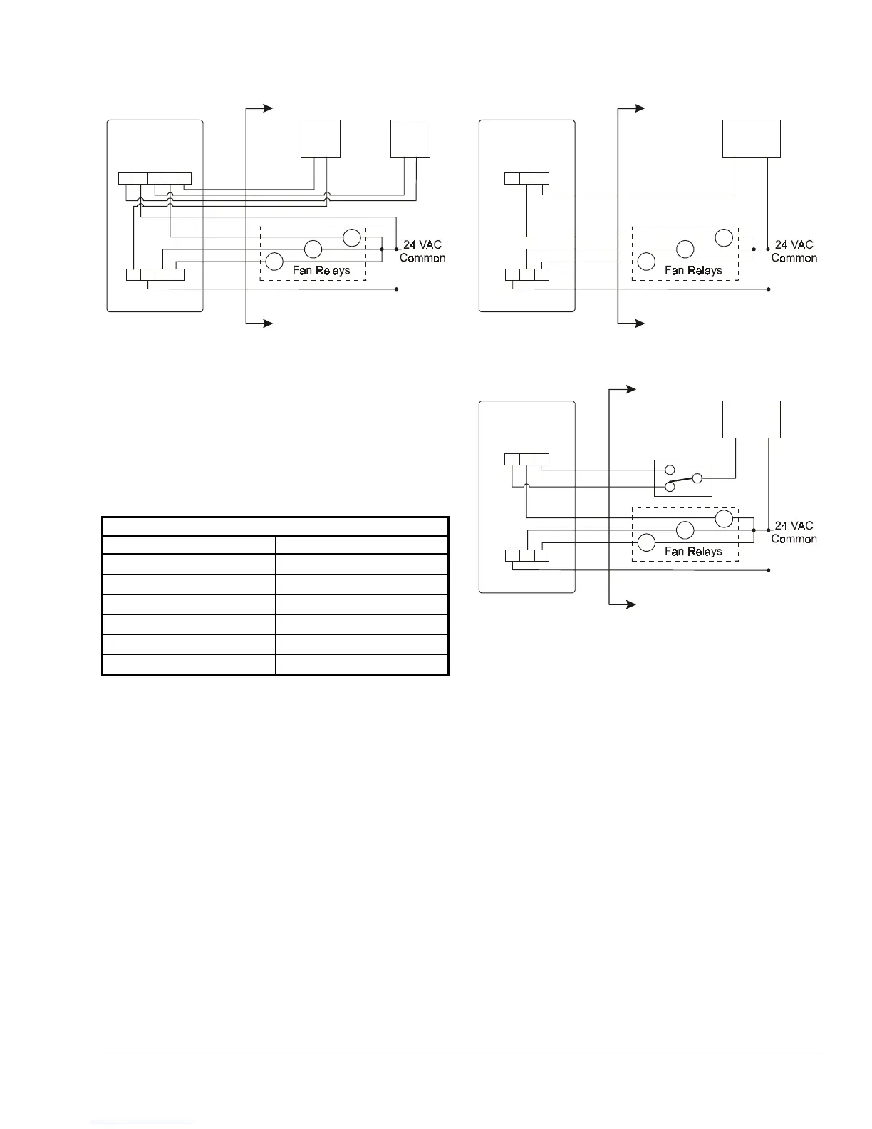
Figure 4: Wiring the T2000ACx-0C0 for
Heating/Cooling Only: 4-Pipe System
with 3-Speed Fan Control
Model T2000ECx-0C0
Wiring terminal designations appear in Table 2 Wiring
connections for typical T2000ECx applications appear
in Figure 5 and Figure 6.
Table 2: T2000ECx-0C0 Wiring Terminals
Model T2000-ECx-0C0
Terminal Number Connection
3
Heating Valve Common
4
High Fan Speed
5
Cooling Valve Common
6
Low Fan Speed
7
Medium Fan Speed
8
24 VAC Power
24 VAC
COOL (C)
Valve
All Wiring to be
Supplied by Installers
LOW
HIGH
MED
System: ON-OFF
Fan:
HIGH-MED-LOW
H
L
M
34
5
678
Figure 5: Wiring the T2000ECx-0C0 for Cooling
Only: 2-Pipe System with 3-Speed Fan Control
24 VAC
All Wiring to be
Supplied by Installers
LOW
HIGH
MED
HEAT (H)/
COOL (C)
Valve
System: ON-OFF
Fan:
HIGH-MED-LOW
34
5
Winter
Summer
Strap-on
Thermostat
678
H
L
M
Figure 6: Wiring the T2000ECx-0C0 for
Heating/Cooling Only: 2-Pipe System with 3-Speed
Fan Control and Automatic Changeover
Troubleshooting
For the ACx thermostat to function properly, the
Heat-Off-Cool switch must be fully in the desired
position. For the ECx thermostat to function, the
ON/OFF switch must be fully in the ON position.
Repairs and Replacement
Do not attempt to repair the T2000 Series thermostat.
In case of an improperly functioning control, contact
the nearest Johnson Controls® representative, and
specify the desired product code number. When
contacting the supplier for a replacement please state
the type/model number of the control located on the
data plate or cover label.
 Loading...