T500 Series Programmable Thermostats Product/Technical Bulletin
13
1st Stage
Cool
2nd Stage
Heat
Heat
Fan
Cooling
W1
Y1
Y2
G
OB
24V(c)
RS1
RS2
Remote
Sensor
(if used)
R
24V
LED1
LED2
T1
T2
2nd Stage
Electronics
COM
OCC
events)
NO NC
COM
UNOCC
(night event
or
if
thermostat
NO
NC
Thermostat
Equipment
Reverse
Valve
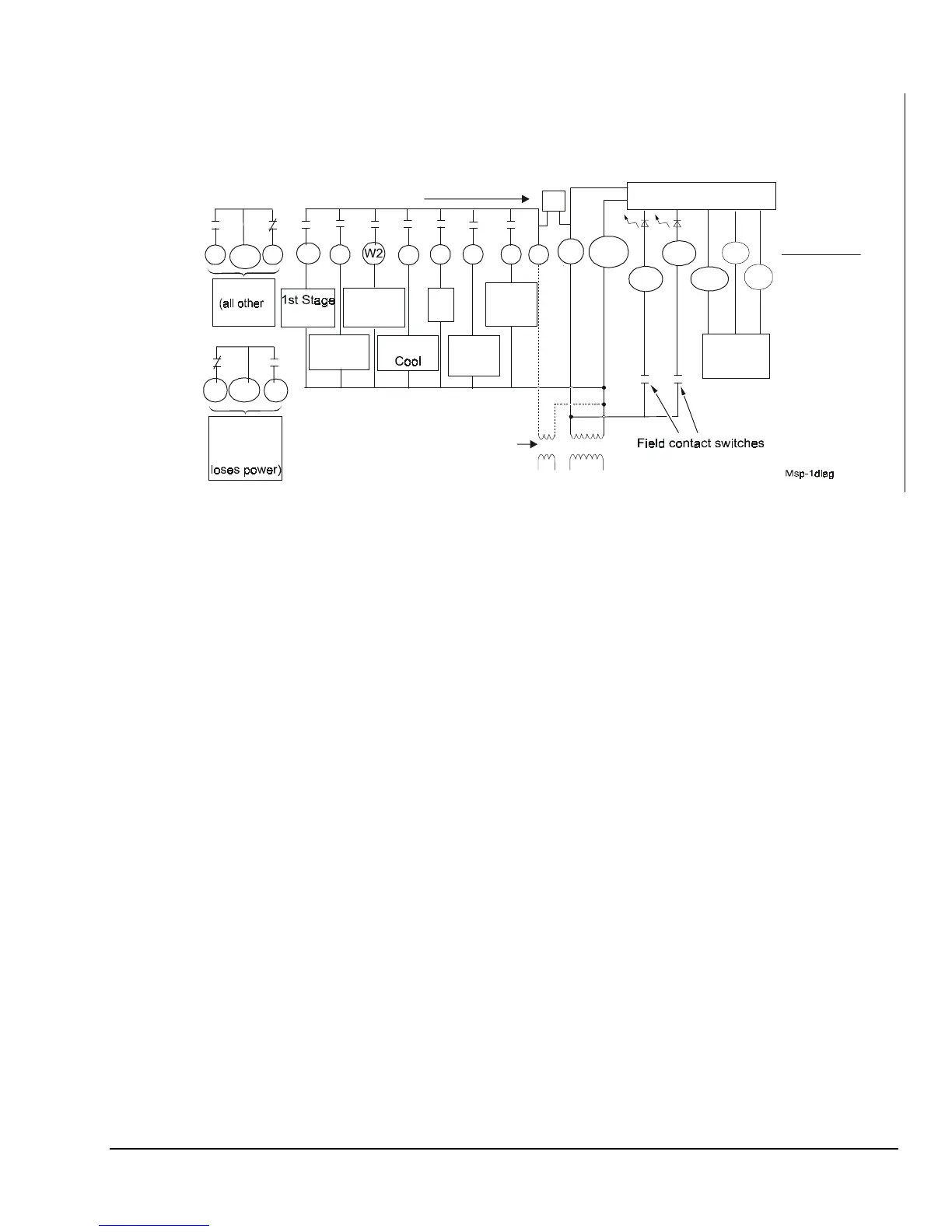
If the transformer (T2) is to power all of the loads,
R and 24V must be connected by inserting jumper
J 1 located above the relays. If a separate 24V
transformer (T1) is to be used, remove the jumper
1 to disconnect R and 24V(c).
P
JP
JP1
optional
Reverse
Valve
Heating
RS+V
Figure 18: T500MSP-1 Wiring Schematic