2
T500 Series Programmable Thermostats Product/Technical Bulletin
I
ntroduction
The T500 thermostats use an adaptive control routine,
based on fuzzy logic, to determine the heating or
cooling load of the controlled space. The routine
calculates load by evaluating recent room conditions
and room reactions to heating and cooling. This load is
used to determine the cycle rate of the equipment,
giving optimal control of the space.
S
upplies Needed
•
drill
•
4.7 mm (3/16 in.) drill bit
•
3 mm (1/8 in.) flat-blade screwdriver
•
hammer
•
marking pencil
•
wire stripper
T500MSP-1
T500HPP-1
T500HCP-1
T500HPP-2
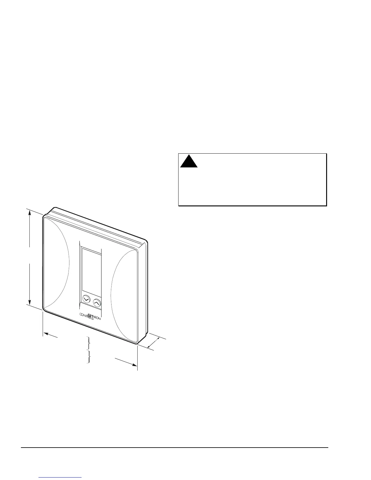
Dimn
114.3
(4-1/2)
127
(5)
101.6
(4)
22.2
(7/8)
Figure 2
:
T500 Dimensions, mm (in.)
L
ocation Considerations
Locate T500 thermostat as follows:
•
on a partitioning interior wall, and approximately
1.5 m (5 ft) above the floor in a location of average
temperature
•
away from direct sunlight or radiant heat, outside
walls or behind doors, air discharge grills,
stairwells, or outside doors
•
away from steam or water pipes, warm air stacks,
unheated/uncooled areas, or sources of electrical
interference
!
CAUTION:
Shock Hazard.
Disconnect power supply before
wiring connections are made to
prevent electrical shock or
possible damage to the
equipment.
I
nstallation and Wiring
Note: When replacing an existing thermostat,
remove and use wire tags to identify terminal
designations.
To install and wire the thermostat:
1. Lift the thermostat cover and insert a small coin
into the slot located in the bottom center of the
thermostat case and twist 1/4 turn. (See Figure 3.)
Grasp the base from the bottom two corners and
separate from the thermostat.
2. Swing the thermostat out from the bottom, and lift
up and out of the base. Place the rectangular
opening in the base over the equipment control
wires protruding from the wall and, using the base
as a template, mark the location of the two
mounting holes. No leveling is required.
3. Use the supplied anchors and screws for mounting
on drywall or plaster. Drill two 4.7 mm (3/16 in.)
holes at the marked locations, tap nylon anchors
flush to wall surface, and fasten. (See Figure 4.)
4. Connect the wires from the existing system to the
thermostat terminals according to wiring
designations in Table 2, Table 3, Table 4, or
Table 5. Push extra wire back into the wall. Wires
must be flush to the plastic base. Plug hole with a
fireproof material to prevent drafts from affecting
ambient temperature readings.
 Loading...