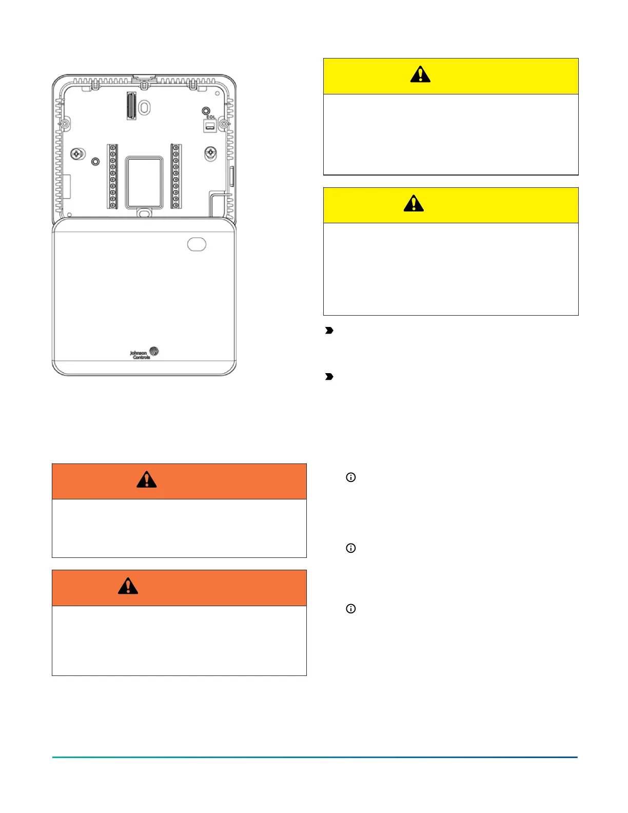
Figure 4: Hanging the thermostat controller front cover
Wiring
About this task:
When you replace an existing thermostat controller,
remove and label the wires to identify the terminal
functions.
WARNING
Risk of Electric Shock
Disconnect the power supply before making electrical
connections to avoid electric shock.
AVERTISSEMENT
Risque de décharge électrique
Débrancher l'alimentation avant de réaliser tout
raccordement électrique afin d'éviter tout risque de
décharge électrique.
CAUTION
Risk of Property Damage
Do not apply power to the system before checking
all wiring connections. Short circuited or improperly
connected wires may result in permanent damage to
the equipment.
ATTENTION
Risque de dégâts matériels
Ne pas mettre le système sous tension avant
d'avoir vérifié tous les raccords de câblage. Des
fils formant un court-circuit ou connectés de façon
incorrecte risquent d'endommager irrémédiablement
l'équipement.
Important: Make all wiring connections in
accordance with local, national, and regional
regulations. Do not exceed the electrical ratings of
the TEC3000 Series Thermostat Controller.
Important: Use correct ESD precautions during
installation and servicing to avoid damage to the
electronic circuits of the thermostat controller.
To wire the thermostat controller, complete the
following steps:
1. Strip the ends of each wire 1/4 in. (6 mm) and
connect them to the appropriate screw terminals as
indicated in Table 5.
Note: For more details on wiring the MS/
TP Communications Bus, refer to the MS/
TP Communications Bus Technical Bulletin
(LIT-12011034).
2. Attach the communication wires to the terminal
block.
Note: If multiple wires are inserted into the
terminals, make sure to twist the wires together
before you insert them into the terminal
connectors.
3. Carefully push any excess wire back into the wall.
Note: Seal the hole in the wall with fireproof
material to prevent drafts from affecting the
ambient temperature readings.
4. For networked models, set the bus end-of-line (EOL)
termination switch to the desired location.
You can designate the thermostat controller as
the end of the Field Controller (FC) Bus and N2
Bus through the bus EOL termination switch.
The default position is OFF. If the thermostat
controller is at the end of a daisy chain of
TEC3000 Series Proportional Fan Coil Thermostats Installation Guide4