- 1 -
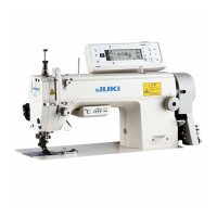
1) Remove side plate setscrews
1
from the s
ide plate.
2) Install control panel
2
on the machine head using screws
5
, at washers
3
and rubber seat
4
sup-
pl
ied with the control panel as the accessories.
1. INSTALLING THE CONTROL PANEL
< The relation between the respective machine heads and the positions of installing hole of the bracket are as described in the table. >
1 2
3 4 5
6
WARNING :
To prevent personal injury caused by abrupt start of the sewing machine, carry out the work after
turning OFF the power switch and ascertaining that the motor has completely stopped.
WARNING :
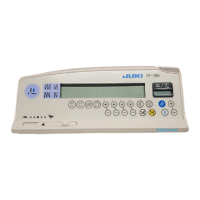
This Instruction Manual is for the control panel, CP-180.
Read "Safety Instructions" of the Instruction Manual for the control box carefully beforehand and
understand them before using CP-180.
In addition, be careful not to splash water or oil on it, or shock such as dropping and the like since
this product is a precision instrument.
1. DDL-9000B (Not provided with AK) is given as an example of installing procedure.
2. Screw to install the panel changes according to the machine head used. Refer to Table 1 and
conrm the kind of screw.
Table 1
Installing hole
Screw
DDL-9000A
1
-
5
M5 X
12
Screw supplied with panel
as accessories
DDL-9000B
1
-
5
(Prov
ided with AK)
M5 X 14
Side plate setscrew
(Not provided with AK)
M5 X 12
Screw supplied with panel
as accessories
LH-3500A
2
-
5
M5 X
14 Side plate setscrew
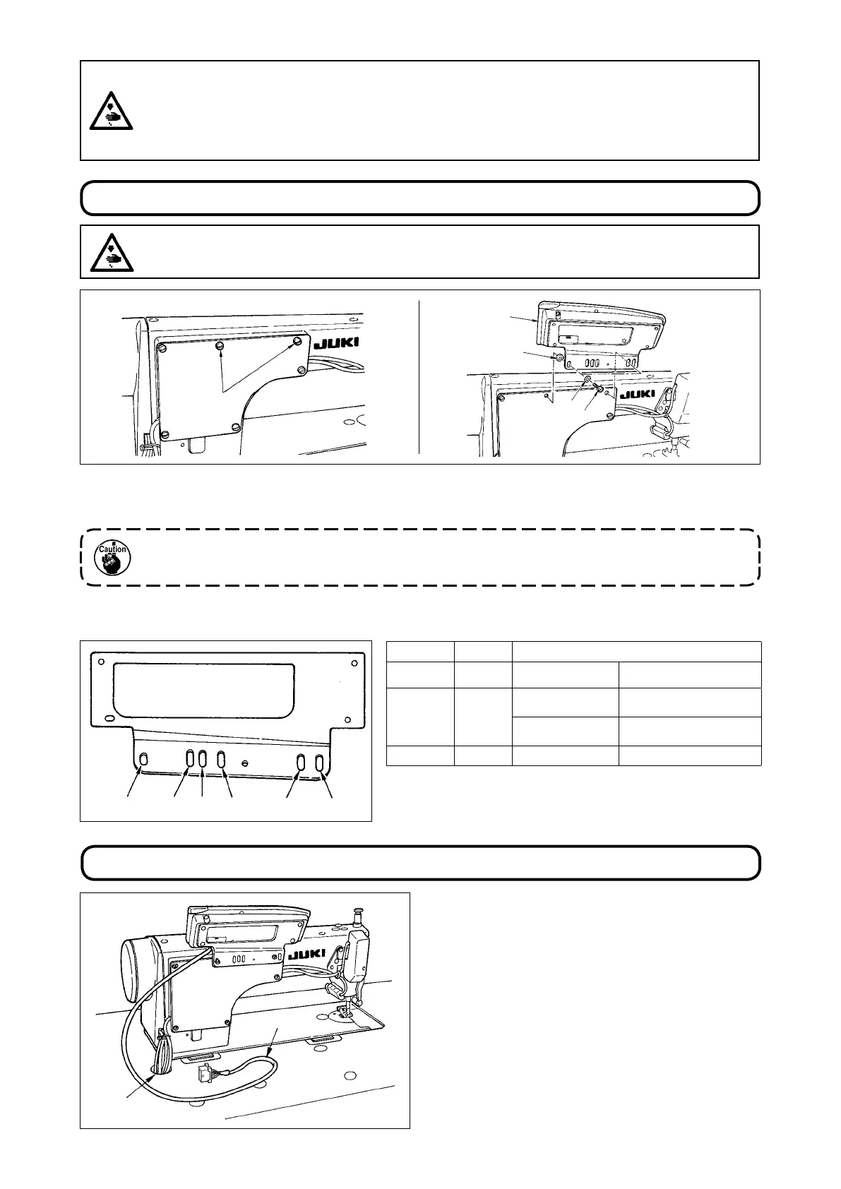
1) Pass cord
1
of the control panel through hole
A
in the machine table route it to the underside of
the table.
2) As for the connection of the connector, refer to
the Instruction Manual for the control box.
2. CONNECTING THE CORD
1
A
1
2
4
5
3
 Loading...