– 1 –
1. INSTALLING THE MACHINE
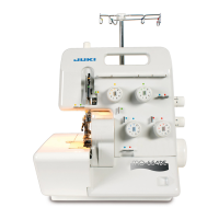
SPECIFICATIONS
1. Carry the sewing machine with two persons.
(Caution) Do not hold the handwheel.
2.
Do not put protruding articles such as the screwdriver and the like at
the location where the sewing machine is placed.
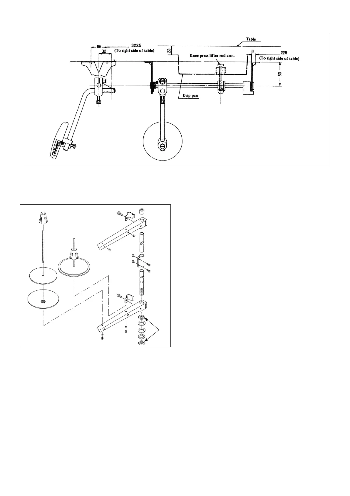
3. Attaching the hinge rubber and the head support rubber, etc.
Fix the hinge rubber
1
, the head cushion washer
2
, the head sup-
port rubber washer
3
and the head support rubber
4
supplied with
the machine on the table using the nails
5
.
Attach the head cushion
6
to the head support rubber
4
.
Stitch type 1-needle, single-thread, chainstitch Needle TV×7 #11 to #14 (standard: #14)
Applications Basting the suits pieces of light and medium-
heavy weight fabrics
Thread take-up Needle bar thread take-up
Sewing speed Max. 1,800 sti/min Looper Single thread looper, looper shaft dia. Ø4.05
Stitch length 2 to 10 mm
(Adjustment is possible to 1 to 10 mm. )
Stitch length adjustment Dial regulator
Lift of presser foot Hand lifter 5.5 mm, Knee lifter 12 mm Lubricating oil JUKI New defrix oil No.1
Noise - Equivalent continuous emission sound pressure level (L
pA
) at the workstation:
A-weighted value of 68.5 dB; (Includes K
pA
= 2.5 dB); according to ISO 10821- C.6.2 -ISO 11204 GR2 at 1,800 sti/min.
5. Fit hinge
9
into the opening in the machine bed, and fi t the ma-
chine head to table rubber hinge before placing the machine head
on rubber seats on the four corners.
6. Securely attach head support rod
!0
to the table until it goes no
further.
9
9
9
!0
1
3
5
5
2
4
6
5
4
6
8
7
23mm
1.5mm
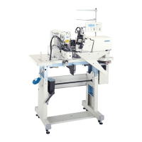
4. Put the drip pan
7
into the machine table
8
from above. Place it
so that its right end has a gap of 1.5 mm from the end of the table
8
and its top end is 23 mm above the table
8
surface.
* Make sure that the recessed part of the knee lifter rotation arm is
located just under the installation hole for the knee press lifter rod
and fi x the drip pan
7
in the above-mentioned position by using 6
wood screws.
 Loading...