Juniper Networks SSG 5 and SSG 20 Security Policy
Interfaces
The SSG 5 and SSG 20 provide a number of interfaces:
• The SSG 5 has seven Ethernet autosensing interfaces (RJ-45); the SSG 20 has four
Ethernet interfaces. (Data Input, Data Output, Control IN, Status OUT). These interfaces
are network ports. Each port has two LEDs that indicate port status:
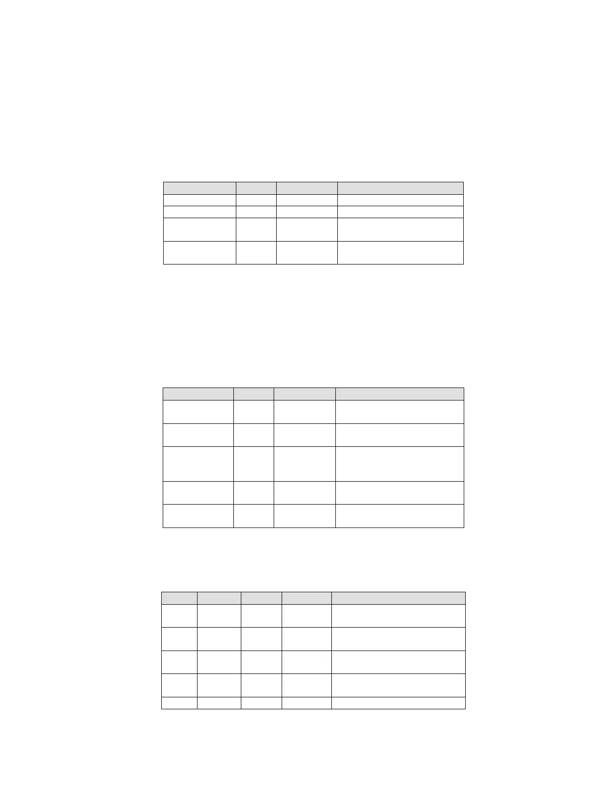
Table 3: SSG 5 and SSG 20 Ethernet Port LEDs
TX/RX (right) Green Blinking Indicates that traffic is
Indicates that no traffic is
passing through.
• Console port – RJ-45 serial port connector (Data Input, Data Output, Status OUT, Control
IN). This port allows initial access to the Command Line Interface (CLI).
• Modem port – RJ-45 serial port connector. Disabled in FIPS mode.
• USB port. Disabled in FIPS mode.
• Power interface: AC or DC.
• The SSG 5 and 20 have four status LEDs. Two LEDs are common to both:
Table 4: Common LEDs to SSG 5 and SSG 20
Indicates that the unit is
receiving power
Indicates that the unit is
not receiving power
Indicates that the system
is starting or performing
Indicates that the device is
operating normally.
Indicates that there was
an error detected
The SSG 5 has two LEDs that indicate the status of the optional integrated WAN link:
Table 5: SSG 5 WAN link status LEDs
ISDN CH B1 Green Steady Indicates that B-Channel 1
Indicates that B-Channel 1
is not active
Indicates that B-Channel 2
is active
Indicates that B-Channel 2
is not active
Indicates that the link is
 Loading...