Information about the heater
? ??? ??? ??? (YYYY/MM)
6
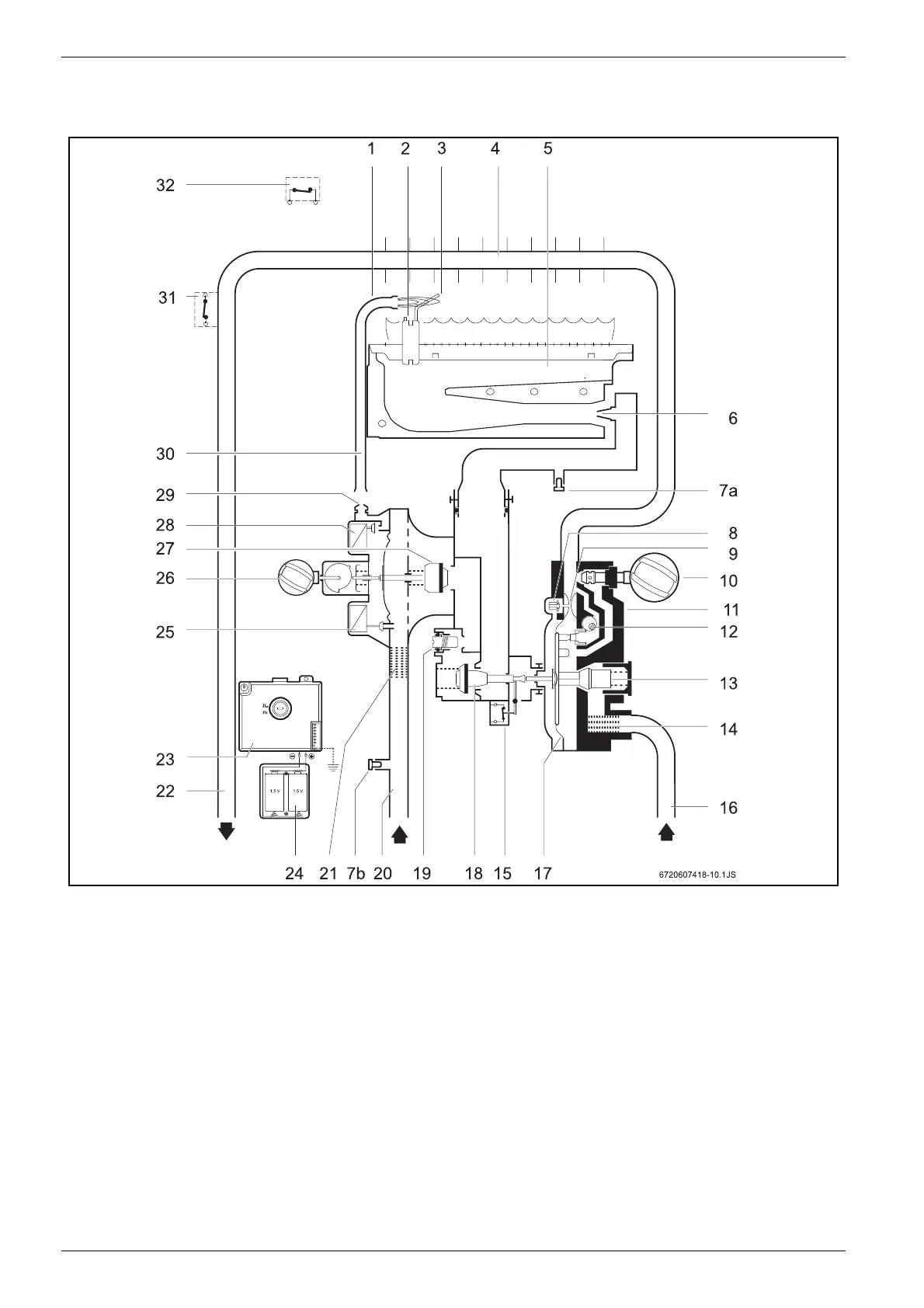
2.7 Functional diagram of the heater
Fig. 2 Functional diagram
1 Pilot burner
2 Spark plug
3 Ionisation probe
4 Combustion chamber
5 Main burner
6 Injector
7a Screw for measurement of pressure in burner
7b Screw for measurement of input pressure
8 Slow ignition valve
9 Venturi
10 Temperature/volume selector
11 Water valve
12 Command cone
13 Water flow regulator
14 Water filter
15 Micro-switch
16 Cold water pipe
17 Diaphragm
18 Main gas valve
19 Maximum gas adjusting screw
20 Gas supply pipe
21 Gas filter
22 Hot water pipe
23 Ignition unit
24 Battery compartment
25 Servo valve
26 Power selector
27 Gas valve
28 Pilot valve
29 Pilot injector
30 Pilot gas pipe
31 Temperature limiter
32 Flue gas safety device
 Loading...