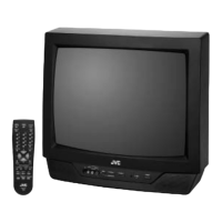
V-20NMG3B
20
ADJUSTMENTS
B1 POWER SUPPLY
Item
Measuring
instrument
Test point Ad justment part Description
Check of
B1 Power
Supply
Signal
generator
DC Volt -
meter
TP-91 ( B1)
TP-E (#
##
#)
1. Inp ut a wh ole black sig na l.
2. Con nect a DC vo lt meter t o TP-9 1( B1) a nd TP-E ( #).
3. M ake sur e t hat th e volt ag e is DC1 16. 5±2.0V.
FOCUS ADJUSTMENT
Item
Measuring
instrument
Test point Ad justment part Description
Ad just ment
of FOCUS
Signal
generator
FOCUS VR
[In HVT]
1. Input a cross-hatch signal.
2. While watchin g th e s creen, ad just the FO CUS V R t o make th e
vertical and ho rizo nta l lin es as f ine a nd sha rp as possible.
3. M ake sur e th at when the screen is d arken ed, the lin es re ma in in
g ood focu s.
IF CIRCUIT ADJUSTMENT
Item
Measuring
instrument
Test point Ad justment part Description
●Please use signal generator which is correct proof about the
sen ding freq ue ncy.
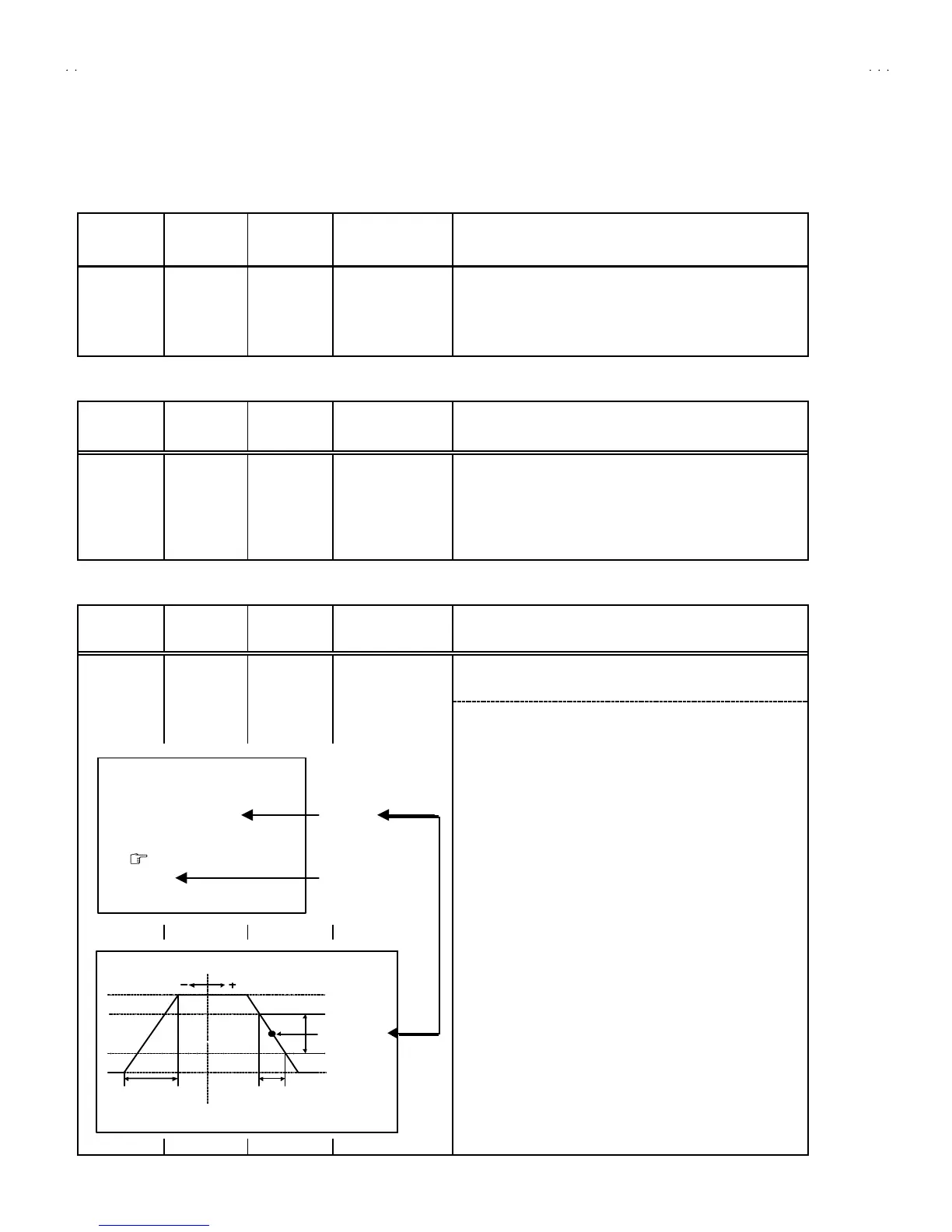
Ad just ment
of VCO
Signal
generator
Remote
control unit
1. VCO
1. Inp ut th e PA L f ull colo ur b ar (210 .25MHz) sig nal.
2. En ter th e SERVICE ME NU.
3. Sele ct 1.IF f rom t he SERVICE MENU.
4. Press 1 key an d s elect 1. VCO.
5. Select VCO ADJ US T with MENU ▲/▼ key.
6. Press MENU -/+ k ey unt il the co lour of t he c haract er s TOO
HIGH ch an ges b lu e to ye llow. Th en g r ad ually press th e MENU
-/+ key u ntil th e TOO LOW ch ang es yellow. At this t ime, conf irm
th at t he valu e of VCO ADJUST is n ear +00 .
7. Select AFT ADJUST with MENU ▲/▼ key.
8. Press MENU -/+ key until the characters JUST REFERENCE
ch ang es b lue to yellow.
9. Press the DI SPLAY key three times to return to normal screen.
VCO (C W)
***.**
MHz
TOO HIGH
AB OVE REFEREN CE
JU ST REF ER ENCE
BELOW R EFEREN CE
TOO LOW
AFT AD JUST
** *(* *)
** *(* *)** *(* *)
** *(* *)
VCO ADJUST
** *(* *)
** *(* *)** *(* *)
** *(* *)
FINE
DISP : EXIT
YE LLOW
D
 Loading...