V-20NMG3B
28
Item
Measuring
instrument
Test point Ad justment part Description
●
●●
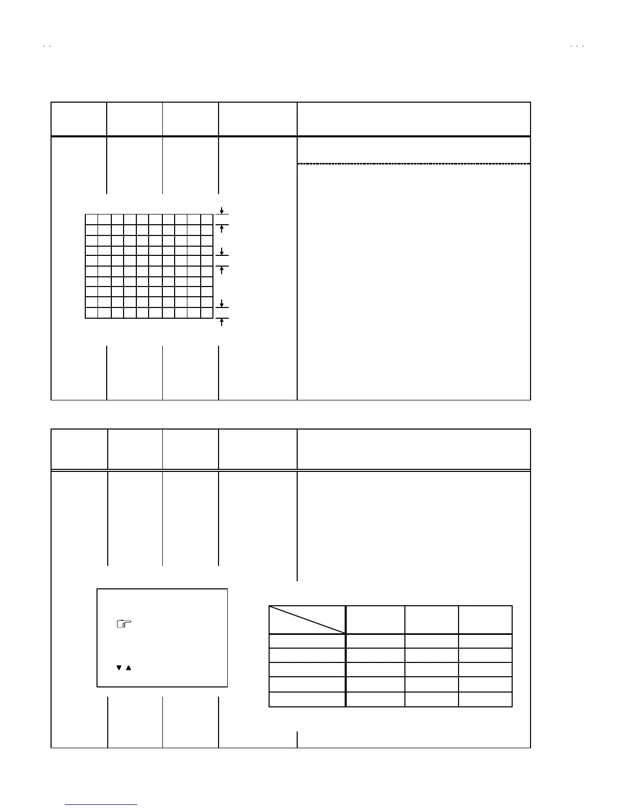
● Whe n the v ertic al linea rity has been dete riorated
rem arkably, perform the following steps.
15 . Inp ut a cr oss -hatch sign al.
16. Sele ct 4. VER. LIN. with the MENU
▼
/
▲
key.
17. Set the initial setting value of 4. VE R LIN. with the MENU - / +
key.
18. Sele ct 5. VER. SCURV E with the MENU
▼
/
▲
key.
19. Set the initial setting value of 5. VER. SCURV E wi t h th e ME NU
- / + key.
20. Adju st 4. VER. LIN. and 5. VER. SCURVE so t hat th e spaces
of each lin e as sh own in Fig. 3 o n TOP, CENTER and
BOTTOM become uniform.
Ad just ment
of VER. LIN.
& VER.
SCURVE
Signal
generator
Remote
control unit
4. VER. L IN.
5. VER. S CURV E
Make su re that th e a djust me nt is pro per ly do ne on t he scre en of
60 Hz mode .
[NOTE]
"
Adjust to make both 50Hz & 60Hz are the same v. size and
fine straight line.
"
When ad just aga in, adju st 5 0Hz m od e fir st.
"
When adjust in 60Hz mode, only 60Hz mode is adjust.
VSM PRESET SETTING
Item
Measuring
instrument
Test point Ad justment part Description
Setting of
VS M
PRES ET
Remote
control unit
TINT
COLOUR
BR IG HT
CONT .
SHARP
1. En ter th e SERVICE ME NU.
2. Select 4. VS M PRESE T from the SERVICE MENU.
3. Sele ct BRIG HT with th e PICTURE MODE ke y.
4. Adjust t he MENU
▼
/
▲
and MENU - / + key to bring the set
valu es of TINT
~
~~
~
SHARP to the values shown in the below
table.
5. Resp ectively s elect the VS M PRES ET mode f or SO FT an d
STANDARD, and make s imilar adjustment as in 3 above.
TOP
CEN TER
BOTTOM
Fig .3
BRI GHT
TINT
COLOUR
BRI GHT
CONT.
 Loading...