No.51818
AV29A10EUS
8
SPECIFIC SERVICE INSTRUCTIONS
DISASSEMBLY PROCEDURE
REMOVING THE REAR COVER
1. Unplug the power plug.
2. As shown in the Fig. 1, remove the
14
screws marked
A
.
3. Withdraw the rear cover toward you.
REMOVING THE CHASSIS
"
After removing the rear cover.
1. Slightly raise the both sides of the chassis by hand and remove
the 2 claws under the both sides of the chassis from the front
cabinet.
2. Withdraw the chassis backward.
(If necessary, detach the wire clamp, connectors etc.)
REMOVING THE AV TERMINAL BOARD
"
After removing the rear cover.
1. As shown in Fig. 1, remove the
3
screws marked
B
.
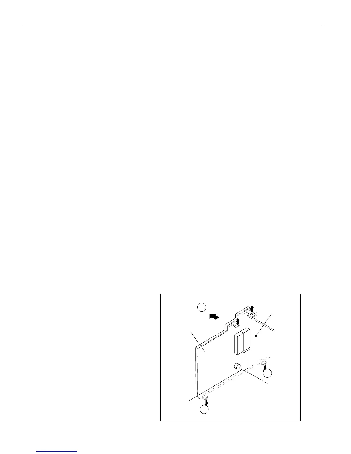
2. As shown in Fig. 2, remove the 2 claws marked
E
under the
CHASSIS.
3. As shown in Fig. 2, remove the AV TERMINAL BOARD slightly in
the direction of the arrow
F
.
REMOVING THE SPEAKER
"
After removing the rear cover and chassis.
1. As shown in the Fig. 1, remove the
2
screws marked
D
.
NOTE : W hen removing the screws marked
D
of the speaker,
remove the lower side screw first. Then remove the upper
one.
2. Remove the 2 screws
C
attaching the speaker.
3. Follow the same steps when removing the other hand speaker.
CHECKING THE PW BOARD
To check the back side of the PW Board.
1) Pull out the chassis. (Refer to REMOVING THE CHASSIS).
2) Erect the chassis vertically so that you can easily check the back
side of the PW Board.
[CAUTION]
"
When erecting the chassis, be careful so that there will be no
contacting with other PW Board.
"
Before turning on power, make sure that the wire connector is
properly connected.
"
When conducting a check with power supplied, be sure to confirm
that the CRT EARTH WIRE (BRAIDED ASS’Y) is connected to
the CRT SOCKET PW board.
WIRE CLAMPING AND CABLE TYING
1. Be sure to clamp the wire.
2. Never remove the cable tie used for tying the wires together.
Should it be inadvertently removed, be sure to tie the wires with a
new cable tie.
AV SW PWB
C
D
AV TERMINAL BOARD
Fig. 2
C
 Loading...