1-24 (No.YA073)
4.8.6 MTS CIRCUIT
Item
Measuring
instrument
Test point Adjustment part Description
MTS INPUT
LEVEL
Remote
control unit
[3.SOUND (A)]
A01: IN LEVEL
(1) Receive the any broadcast.
(2) Select the 3.SOUND (A) from the SERVICE MODE.
(3) Select the < A01 > (IN LEVEL).
(4) Set the intal setting value of the < A01 >.
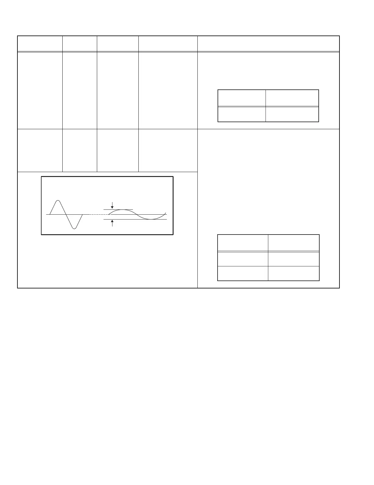
MTS
SEPARATION
TV audio
multiplex
signal
generator
Oscilloscope
R OUT
L OUT
[AUDIO OUT]
[3.SOUND (A)]
A02: LOW SEP.
A03: HI SEP.
(1) Input the stereo L signal (300Hz) from the TV audio
multiplex signal generator to the antenna terminal.
(2) Connect an oscilloscope to R OUT pin of the AUDIO
OUT, and display one cycle portion of the 300Hz
signal.
(3) Select the 3.SOUND (A) from the SERVICE MODE.
(4) Select the < A02 > (LOW SEP.).
(5) Set the initial setting value of the < A02 >.
(6) Adjust the < A02 > so that the stroke element of the
300Hz signal will become minimum.
(7) Change the connection of the oscilloscope to L OUT
pin of the AUDIO OUT, and enlarge the voltage axis.
(8) Change the signal to 3kHz, and similarly adjust
the < A03 > (HI SEP.).
S
etting
item
A01: IN LEVEL
Initial setting value
12
A02: LOW SEP
S
etting
item Initial setting value
39
A03: HI SEP
16
L-Channel
signal waveform
R-Channel
crosstalk portion
Minimum
1 cycle
 Loading...