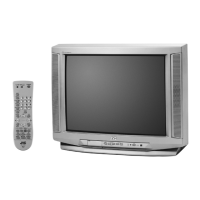
1-8 (No.YA073)
3.2 MEMORY IC REPLACEMENT
• This model uses the memory IC.
• This memory IC stores data for proper operation of the video and drive circuits.
• When replacing, be sure to use an IC containing this (initial value) data.
3.2.1 MEMORY IC REPLACEMENT PROCEDURE
1. Power off
Switch off the power and disconnect the power plug.
2. Replace the memory IC
Be sure to use a memory IC written with the initial setting data.
3. Power on
Connect the power cord to the wall outlet and switch on the
power.
4. Receiving channel setting
Refer to the OPERATING INSTRUCTIONS (USER'S GUIDE)
and set the receive channels (Channels Preset) as described.
5. User settings
Check the user setting items according to the "FACTORY
SETTING ITEM" table.
Where these do not agree, refer to the OPERATING
INSTRUCTIONS (USER'S GUIDE) and set the items as
described.
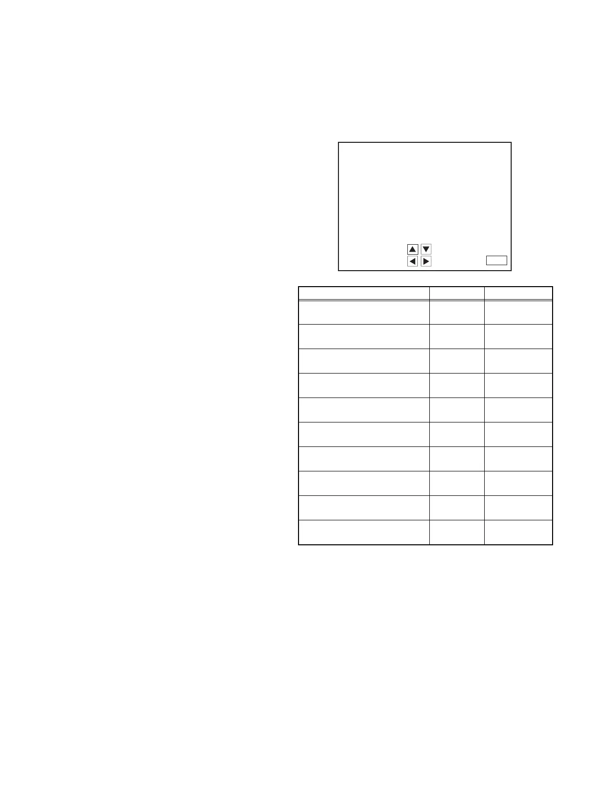
6. SERVICE MODE setting
Verify what to set in the SERVICE MODE, and set whatever is
necessary(Fig.1) .
Refer to the SERVICE ADJUSTMENT for setting.
3.2.2 SERVICE MODE SETTING ITEMS
Fig.1
Setting items Settings Item No.
1. V/C
(Video setting)
Adjust S01~S48
2. DEF
(Deflection setting)
Adjust D01~D33
3. SOUND(A)
(Audio setting)
Adjust A01~A08
4. OTHERS [Do not adjust]
(Factory setting)
Fixed F01~F18
5. 3L Y/C [Do not adjust]
(Y/C Separate setting)
Fixed LYC01~LYC12
7. LOW LIGHT
(White balance setting)
Adjust ---
8. HIGH LIGHT
(White balance setting)
Adjust ---
9. VCO
(VCO setting)
Adjust ---
11. I2C BUS [Do not adjust]
(I
2
C BUS setting)
Fixed ---
12.SYSTEM (SYS)
(System constant setting)
Fixed SYS01~SYS25
1.
3.
5.
7.
9.
11.
2.
4.
8.
12.
SERVICE MENU
DEF(D)
OTHERS(F)
HIGH LIGHT
SYSTEM(SYS)
SELECT BY
OPERATE BY
EXIT BY
EXIT
SERVICE MENU
V/C(S)
SOUND(A)
3L Y/C(LYC)
LOW LIGHT
VCO
I2C BUS
 Loading...