(No.MB396)1-11
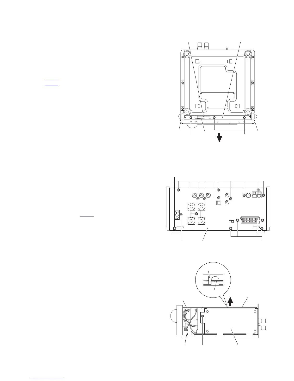
3.1.3 Removing the front panel assembly
(See Fig.8)
• Remove the top cover, AL panel L and AL panel R.
(1) Removing the three screws J attaching the front panel as-
sembly. (See Fig.8.)
(2) Release the claws a attaching the front panel assembly
and remove the front panel assembly in the direction of the
arrow. (See Fig.8.)
Note:
When attaching the front panel assembly, confirm that the con-
nector CN804
on the front board is disconnected in the con-
nector CN704 on the micom board certainly.
Fig.8
3.1.4 Removing the rear panel
(See Fig.9.)
From the back side of the main body, remove the fifteen screws
K and screw L attaching the rear panel.
3.1.5 Removing the switching power unit
(See Figs.9 and 10)
• Remove the top cover, AL panel L and AL panel R.
(1) From the back side of the main body, remove the screw L
attaching the switching power unit. (See Fig.9.)
(2) From the right side of the main body, disconnect the wire
from the connector CN201
on the main board. (See
Fig.10.)
(3) Remove the screw M attaching the switching power unit.
(See Fig.10.)
(4) From the top side of the switching power unit, remove the
spacer fixing the lug wire. (See Fig.10.)
(5) Take out the switching power unit from the main body in the
direction of the arrow. (See Fig.10.)
Fig.9
Fig.10
J
a
a
Front panel assembl
J
CN804
CN704
K
KL
Rear panel
M
Switching power unit
CN201
Main board
Wire
Spacer
Lug wire
 Loading...