1-3
1
COVER(ZOOM) Fig.1-3-1 (S1a),(S1b),2(L1a),2(L1b ) -
ASSY
2
UPPER CASE ASSY
Fig.1-3-2 4(S2a),3(S2b),(L2),(S2c) NOTE2
( Inc.E.VF UNIT (S2d)
(B/W),SPEAKER/ CAP(DC JACK)
MONITOR) 聽CN2
3
FRONT COVER Fig.1-3-3 (S3a),2(S3b),(L3a) NOTE3a
ASSY (Inc.MIC) (L3b),聽CN3 NOTE3b
4
OP BLOCK ASSY Fig.1-3-4 聽CN4a,CN4b,CN4c-
/BRACKET(OP) 3(S4)
ASSY
5
OP BLOCK ASSY Fig.1-3-5
/
6
JACK BOARD ASSY
3(S6)
/
7
FRAME ASSY 2(S7)
8
REAR UNIT Fig.1-3-6 聽CN8 NOTE8
4(S8)
9
LOWER CASE ASSY
Fig.1-3-7 聽CN9 -
(Inc.ZOOMUNIT) (S9a),4(S9b),(L9a),(L9b)
0
JUNCTION BOARD
Fig.1-3-8 聽CN0a,CN0b,CN0c NOTE0a
ASSY 2(S0),聽CN0d NOTE0b
!
MAIN BOARD ASSY
Fig.1-3-9 (S!a),(L!a),SHIELD PLATE -
/ 聽CN!a,CN!b,CN!c
@
/MECHANISM ASSY
2(S!b),(L!b)
#
E.VF UNIT Fig.1-3-10 聽CN#,(S#a),(S#b) NOTE#a
(L#) NOTE#b
$
MONITOR ASSY Fig.1-3-11 3(S$a),COVER(HINGE) NOTE$
/ 聽CN$, 2(S$b)
%
MONITOR BOARD (S%a),PLATE(SPK), NOTE%
ASSY 3(S%b),(L%)
STEP
No.
PART
Fig.No.
POINT NOTE
1.3.2 Disassembly method
Table 1-3-2
----------------- --------------------------------------
NOTE
2
:
Remove the CAP (DC JACK) before removing
these parts .
NOTE
3
a:
As it is difficult to remove (L
3
b), remove the
F. COVER ASSY by lowering it.
NOTE
3
b:
Be careful not to damage any parts.
Particularly, take care not to scratch or stain the
lenses.
NOTE
8
:
As screw No. 24 is hidden behind the cassette
cover, open the cassette cover to enable re-
moval of the screw.
NOTE
0
a:
As the CN572 is located at the back of the as-
sembly, unplug the three connectors and re-
move the screws before disconnecting the
CN572.
NOTE
0
b:
Be careful not to damage any of the switches.
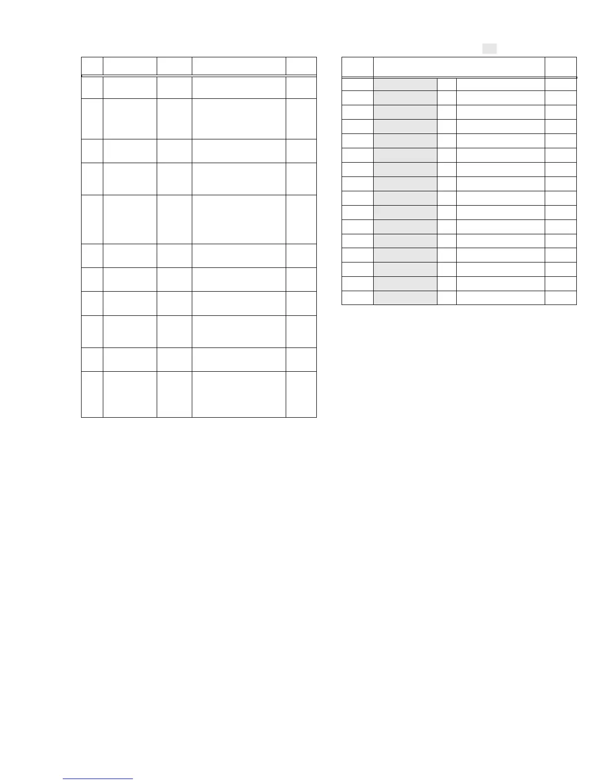
CONN.
No.
Pin No.
CONNECTOR
Table 1-3-3
Note:
Remove the parts marked in .
CN2 MAIN CN101 ⇔ MONITOR CN761 40
CN3 MAIN CN106 ←→ MIC — 3
CN4a MAIN CN107 ⇔ CCD — 20
CN4b MAIN CN108 ⇔ OP BLOCK ASSY — 22
CN8 MAIN CN104 ←→ REAR UNIT CN1 10
CN9 MAIN CN109 ⇔ ZOOM UNIT — 15
CN4c JACK CN502 ⇔ MAIN CN103 20
CN0a JUNCTION CN571 ⇔ MAIN CN113 34
CN0b JUNCTION CN574 ⇔
LOADING MOTOR
—6
CN0c JUNCTION CN573 ⇔ DRUM MOTOR — 11
CN0d JUNCTION CN572 ⇔ SENSOR — 15
CN!a MAIN CN110 ⇔ HEAD — 8
CN!b MAIN CN112 ⇔ CAPSTAN MOTOR — 18
CN!c MAIN CN111 ⇔ ROTARY ENCODER — 6
CN# MONITOR CN763 ⇔ E.VF UNIT (B/W) CN721 20
CN$ MONITOR CN764 ⇔ LCD BL CN751 33/32
----------------- --------------------------------------
----------------- --------------------------------------
NOTE
#
a:
To remove the unit, unlock the connector and
pull out the unit together with the FPC.
NOTE
#
b:
When removing the unit, insert the FPC into the
gap.
NOTE
$
:
When reassembling the MONITOR ASSY, be
careful not to damage any of the parts.
NOTE
%
:
Be careful not to damage any of the parts.
 Loading...