1-10
Fig. 1-5-2
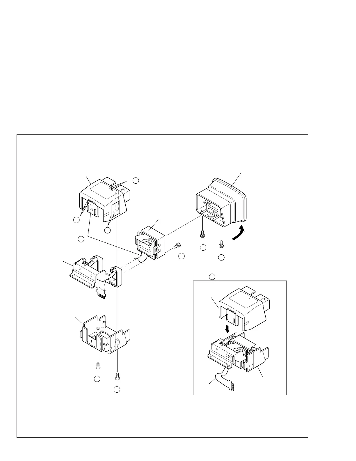
3. Remove the screw (5) and then remove the LCD assem-
bly.
1.5.2 Disassembly/assembly of E. VF assembly
(for COLOR VF)
Note:
Place the E. VF assembly with the VF case (upper)
assembly down through the disassembly/assembly
work.
1. Remove the two screws (1, 2) and the eyepiece assem-
bly while disengaging the hook (L5a).
2. Remove the two screws (3, 4). And spread one side of
the top case sub-assembly to disengage the hooks
(L5b, L5c) that are located at both sides of the top case
sub-assembly, then remove the top case sub-assembly.
Note
5
c:
When removing the top case sub-assembly, peel
off or unplug the FPC that is bonded to the sub-
assembly.
Note
5
d:
When reassembling the top case sub-assembly,
be careful not to catch the FPC between any of
the parts.
TOP CASE
SUB ASSY
FPC
LCD ASSY
TOP CASE SUB ASSY
HINGE ASSY
EYE PIECE ASSY
BOTTOM CASE
(L a)
5
NOTE d
5
5
(S b)
5
1
(S a)
5
2
(S a)
5
4
(S a)
5
3
(S a)
5
(L b)
5
(L c)
5
FPC
NOTE c
5
∗
: 0.069 N
•
m (0.7 kgf
•
cm)
∗
∗
∗
∗
∗
HINGE ASSY
 Loading...